Feature Type
CAD Select Method (CAD View)
Target Point Method (Live View)
 Surface Point
Click once on a surface (Surface Mode) or three times on a wireframe (Curve Mode)
Click once to automatically add a point at the clicked spot on the surface.
 Edge
Point
Edge
Point
Click once near an edge
Click once to automatically add a point on the nearest edge.
 Line
Line
Click once on one end of a line and again at the other end.
Click to locate the start and end points of the line, or double click to automatically add two points at the extent of the current edge.
 Circle
Click once near the edge of the circle.
Click to add three points around the circle, or double click to automatically add three points equally spaced around the circumference of the visible circle.
 Ellipse
Click once near the edge of the ellipse.
Click to add five points around the ellipse, or double click to automatically add five points equally spaced around the visible ellipse.
 Square Slot
Click once near the edge of the square slot.
Click two points on one of the two longer side edges, then click one point on one of the two end edges, then once on the other longer side edge, then finally once on the other end edge.
 Round Slot
Click once near the edge of the round slot.
Click three points on the first arc, and then three more points on the opposite ended arc.
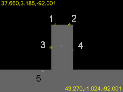
 Notch Slot
Click once near the edge, opposite the notch opening.
Click five points as follows: Two points (1 and 2) on the edge opposite the opening; two points (3 and 4) on each of the parallel sides of the notch; one point (5) on the edge just outside the notch.
 Polygon
Click once near the edge of the polygon.
Click two points on the first side, and then one click on all the other sides. You must set the Number of sides parameter in the Auto Feature dialog box before clicking.
 Profile 2D
Curve Mode: Click on a series of one or more connected edges or arcs using wireframe curve data (Curve Mode).
Surface Mode: Click on a cad entity near the edge and it will build the feature from that and all interconnecting cad elements.
Click sufficient points to define the shape of the profile, with each pair of points being joined by an arc or line. You can insert more points later by right clicking on the Target and selecting Insert Nominal Segment.
Or, double click in the Live View image to edge trace. See the "Using 2D Profile Edge Tracer" topic.
 Blob
Blob
Click once on a surface.
Click once to locate the blob center.