You can rotate, size, or move the gage on the graphical representation of the part. Once you correctly position the gage over a feature and size it to fit the shape of the feature, the software dynamically updates information on the gage in the Probe Toolbox as well as the overlay in your Vision tab. You can then use this information as the nominal values of the feature.
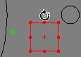
Rotate a Gage: If there's a green dot on the gage, position the pointer over the green dot. The pointer changes to a rounded arrow. Click and drag to perform a 2D rotation of the part in either the left or right direction.
Sample rectangular gage being rotated
Laterally Sizing Gages: If there's a red dot on the gage, position the pointer over a red dot until the pointer changes to a two-way arrow. Click and drag the gage to laterally size the gage either larger or smaller.
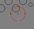
Sample circular gage being sized
The Radius Chart gage and the Grid Chart gage don't have a red dot. To size these gages, select a part of the gage and drag it.
Moving Gages: Position the pointer over the red crosshair at the middle of the gage until the pointer changes to a four-way arrow. Click and drag the pointer to move the gage to a new location. You can also click anywhere on the part and PC-DMIS Vision moves the gage to where you clicked.
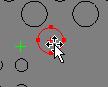
Sample circular gage being moved