Probe Toolbox - Sample Contact Sample Hits Properties tab for a Corner Point Auto feature

Probe Toolbox - Sample Contact Sample Hits Properties tab for a Circle Auto feature
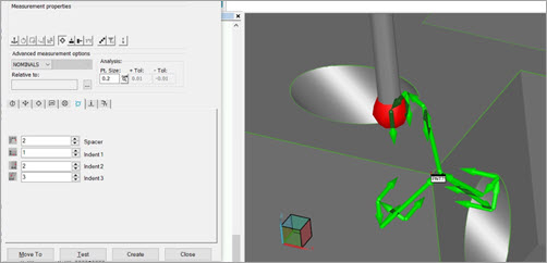
The Contact Sample Hits Properties tab becomes visible when you have the Auto Feature dialog box open and a contact probe is active. This tab contains items that allow you to change the sample hits or sample feature properties for Auto features that use contact probes.
Sample hits measure the surface around the nominal point location, providing a sampling of the surrounding material. This serves the following purposes:
To adjust the path of the feature - Because sheetmetal parts can bend or flex, their measured location can differ quite a bit from the nominal. Sample hits can account for this by adjusting the path of a feature so that the hits are taken at the feature's correct location on the part.
To change the plane that the feature is projected onto - All Auto features that use sample hits are projected onto the plane generated from the sample hits. The reason for this is sometimes the nominal location for a feature does not lend itself to a good hit.
Suppose you want to measure very top of a hole as a Circle feature. Trying to actually take hits on the lip of that hole would result in unreliable hit data. Using a projected plane, however, solves this problem by automatically projecting more reliable hits taken below the surface onto that plane.
A sample feature does the same thing as sample hits, but it provides you with an added benefit of measuring and using a single feature as the feature to project onto instead of using sample hits for each feature.
Suppose you have 10 holes to measure, but you don't need sample hits for each individual circle. You could define a single plane feature as a reference feature. PC-DMIS can measure that plane once and project all the circles' measured hits onto that plane, saving time usually taken by sample hits.
These Auto features support projection features: Surface Point, Circle, Cone, Cylinder, Ellipse, Polygon, Round Slot, Square Slot, and Line.
With sample hits and sample features, you can only use one or the other, not both. They both accomplish the same thing.
A useful way of visualizing how these sample hit properties
affect the measurement is to display path lines and hits by using the
Show
Hit Targets icon ( ).
).
Depending on the type of feature in the Auto Feature dialog box, this tab may change to contain one or more of the following items.
Sample Hits
This item supports the Surface Point, Edge Point, Angle Point, Line, Circle, Ellipse, Round Slot, Square Slot, Notch Slot, Polygon, Cylinder, Cone, and Sphere Auto features. Choosing this item enables the Sample Hits list and disables the Projection Feature items. You can use the Sample Hits list to select the number of sample hits taken for the Auto feature. These hits are used to measure the plane around the nominal point location, providing a sampling of the surrounding material. These are permanent sample hits. For more information on sample hits, see "Sample Hits - Feature Specific Information".
Sample Hits Init
This item supports the Surface Point, Edge Point, Angle Point, Line, Circle, Ellipse, Round Slot, Square Slot, Notch Slot, Polygon, Cylinder, Cone, and Sphere Auto features. By default, this list does not appear in the user interface because initial sample hits are used so infrequently. You can turn it back on using the PTPSupportsSampleHitsInit entry in the PC-DMIS Settings Editor.
You can use this item to specify initial sample hits. The initial sample hits are taken only on the initial measurement of the feature during execution of the measurement routine.
Spacer
This item supports the Surface Point, Edge Point, Angle Point, Line, Corner Point, Plane, Circle, Ellipse, Round Slot, Square Slot, Notch Slot, Polygon, Cylinder, and Cone Auto features. It defines the distance from the nominal point location that PC-DMIS uses to measure a plane if sample hits are specified. For more information, see "Spacer - Feature Specific Information".
Indent
This item supports the Edge Point and Notch Slot auto features. For an Edge Point, it defines the minimum offset distance from the point location to the first sample hit. For a Notch Slot, it defines the distance from the closed side of the notch (opposite the open edge). See "Indent - Feature Specific Information".
Indent 1
This item supports the Angle Point, Line, and Corner Point Auto features. For an Angle Point and Corner Point, it defines minimum offset distance from the feature's center location to the first of two or three sample hits. For a Line, it defines the offsets distance from the line's end points to the second and third sample hits when three sample points are defined. See "Indent - Feature Specific Information".
Indent 2
This item supports the Angle Point, Line, and Corner Point Auto features. For an Angle Point and Corner Point, it defines minimum offset distance from the feature's center location to the second of two or three sample hits. For a Line, it defines the offset distance from the line's midpoint to the first sample hit. See "Indent - Feature Specific Information".
Indent 3
This item supports the Corner Point Auto feature. It defines the minimum offset distance from the feature's center location to the third of three sample hits. See "Indent - Feature Specific Information".
Sample Feature
The Sample Feature item supports the Surface Point, Circle, Cone, Cylinder, Ellipse, Polygon, Round Slot, Square Slot, Notch, and Line Auto features. It enables the feature list below it and disables the Sample Hits items. The feature list contains all the existing features in your measurement routine that you can use as a sample feature. The current feature's hits are projected onto the selected feature. If set to <None>, no projection takes place.
Auto Feature |
Sample Hits Description |
| Angle Point | The sample hits are used on each surface. PC-DMIS measures the point depending on the selected value. For example, if you select:
Two and three sample hits for an Angle Point Auto feature |
| Circle, Cone, or Cylinder | The defined sample hits are used to measure the surface normal to the feature. They are equally spaced between the starting and ending angle indicated. PC-DMIS measures the feature depending on the selected value:
A - Start angle and end angle
A - Start angle PC-DMIS expects the X, Y, Z nominal of the stud to be at the base. If the center point is at the top of the stud, set the depth and spacer to a negative value. |
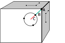
| Corner Point | The SPACER value defines the radius of the circular pattern of the three hits. PC-DMIS centers the circular pattern at the INDENT + SPACER location for each surface.
A - Target corner B - Indent C - Spacer
Example of Corner Point Auto feature sample hits in PC-DMIS |
Edge Point |
PC-DMIS measures the point depending on the selected value. For example, if you select:
Various sample hits for Edge Point Auto features A - Target hit |
| Ellipse | The only acceptable values are zero, one, and three. The measured plane is used as the centerline vector for projection and measurement depth purposes. PC-DMIS measures the ellipse depending on the entered value. For example, if you selected:
To take the hit on the opposite side of the ellipse, reverse the centerline vector. |
| Line | PC-DMIS measures the line depending on the selected value. For example, if you select:
One and three sample hits for a Line Auto feature. The indent 1 (for points 2 and 3) and indent 2 (for point 1) values should not be identical. |
Notch Slot |
The sample hits also define the edge for the angle vector and width. The only acceptable values are zero through five. The measured plane is used as the centerline vector for projection and measurement depth purposes. PC-DMIS measures the notch depending on the entered value. For example, if you selected:
|
Polygon |
PC-DMIS measures the polygon depending on the selected value. For example, if you select:
Example Polygon Auto feature (hexagon) with one sample hit
Example Polygon Auto feature (hexagon) with three sample hits |
Round Slot or Square Slot |
The measured plane is used as the centerline vector for projection and measurement depth purposes. PC-DMIS measures the slot depending on the entered value. For example, if you select:
Sample hits of three hits for a Square Slot Auto feature (top diagram) and a Round Slot Auto feature (bottom diagram) To take the hits on the opposite side of the slot, reverse the centerline vector. Change to Sample Hit Pattern of Round and Square Slots in PC-DMIS v2015 and Later In PC-DMIS v2015 and later, the method for distributing the sample hit pattern for round and square contact slots changed. Two of the hits along the same line along the edge of the slot are now spaced the full length of the slot.
Example 3-hit sample hit pattern (Legacy on left, v2015 and later on right) The change of the sample hit pattern for round and square slots is applied only when the following conditions are met:
Measurement routines created in versions prior to v2015 that contain round or square slots retain the legacy pattern for sample hits. The exception is if you make relevant changes to the slot values requiring a path recomputation from the dialog box that appears after you press the F9 key. |
| Sphere | For a sphere, you can only select one sample hit. When you select this sample hit, PC-DMIS follows this procedure once you execute the measurement routine:
PC-DMIS takes these four hits and uses the calculated sphere location to measure the sphere with the given number of hits, rows, and angles. |
Surface Point |
PC-DMIS measures the point depending on the selected value. For example, if you select:
|
Auto Feature |
Spacer Description |
| Surface Point | The Spacer box defines
the radius of the circle on which the nominal (A) and the sample
points (B) lie.
Nominal and sample points |
Edge Point |
The Spacer box defines the radius of an imaginary circle on which the nominal and the sample points lie.
A - Target hit |
Angle Point |
The Spacer box defines the offset distance between the points on each side of the bend.
A - Indent |
Line |
The Spacer box defines the distance away from the original locations for points 2 and 3 when three sample points are defined. A positive value moves the points towards each other, while a negative value moves them further away.
A - Indent 2 If a single sample point is used, it does nothing. |
Corner Point |
The Spacer box defines the distance from the radius of the first hit to the other hits.
A - Target corner |
Circle, Cylinder, or Cone |
The Spacer box defines the distance from the circumference of the circle to the sample hits.
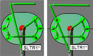
A - Sample hits Notes for Outer Cylinders (studs):
This stud has a top nominal point and a negative spacer value. The three sample hits (indicated by the red lines) are taken on top of the Cylinder Auto feature.
This stud has a top nominal point and a positive spacer value. The three sample hits are taken on the surface around the Cylinder Auto feature. |
Square Slot, Round Slot, or Ellipse |
The Spacer box defines the distance from the outer edge of the feature to the sample hit (or hits).
Spacer for a Square Slot or Notch Auto feature (top)
Spacer for a Round Slot Auto feature A - Sample hits |
| Plane | The Spacer box defines the distance between the hits making up the plane. |
| Notch Slot | The Spacer box defines the distance from the edges of the notch where the sample hits are taken.
Spacer (dotted lines) for a Notch Slot Auto feature with two sample hits |
Polygon |
The Spacer box defines the distance from the edges of the polygon where the sample hits are taken.
Spacer (dotted lines) for a Polygon Auto feature with three sample hits (larger dots) |
Auto Feature |
Indent Description |
Edge Point |
The Indent box displays the minimum offset distance from the point location to the first hit on each side of the bend (or edge).
Offset distance from edge A - Target hit |
Angle Point |
PC-DMIS provides two indent boxes, Indent 1 and Indent 2, in order to set the offset distances from the point location to the sample hits on each of the two surfaces of the bend in an angle point.
Indent in an Angle Point Auto feature A - Indent
|
Line |
PC-DMIS provides two indent boxes, Indent 1 and Indent 2, to set the offset distances for the one or three sample hits for a line.
Indents in a Line Auto feature
The values for Indent 1 and Indent 2 must be different in order to yield a proper sample plane. |
Corner Point |
PC-DMIS provides three indent boxes, Indent 1 and Indent 2, and Indent 3 in order to set the offset distances from the point location to the sample hits on each of the three surfaces of the bend in a corner point.
Indent for a Corner Point Auto feature. For one of the surfaces, 1 shows the indent point, 2 and 3 are the sample hits A - Target corner |
Notch Slot |
The Indent box defines where along the two parallel sides of the notch PC-DMIS takes the hits. It is the distance from the closed side of the notch, moving towards the open side.
Indent for a Notch Slot Auto feature (dotted lines) If you click on the CAD to automatically create the Notch Slot, PC-DMIS automatically generates the indent value based on the size of your probe tip. You can later modify this if desired.
|