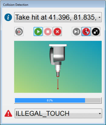
Collisions are shown in the Collision Detection dialog box (Operation | Graphic Display Window | Collision Detection).
Collision Detection dialog box
Most of the items in this dialog box function like those in the Execution dialog box. For information on those items, see "Using the Execution Dialog Box" in the "Using Advanced File Options" chapter.
The following items only apply to collision detection:
Stop On Collision
 - If selected (highlighted), the probe animation
collision detection stops if a collision occurs.
- If selected (highlighted), the probe animation
collision detection stops if a collision occurs.
Probe Display - Immediately below the icons on the dialog box in the probe display area. The probe is shown using a green color. If a collision occurs, the portion of the probe that collides is shown in red. The same color scheme is used to draw the probe on the screen, as well as in the Collision Detection dialog box.
You can enlarge or shrink the drawing of the probe just as you would the part on the Graphic Display window by right-clicking above or below an imaginary horizontal line.
You can 3D rotate the drawing of the probe by holding down Ctrl key on your keyboard and the right-mouse button while dragging the mouse.
Scale to Fit  - Shrinks or enlarges the drawing of the probe so that
it fits back into the probe display area of the dialog box.
- Shrinks or enlarges the drawing of the probe so that
it fits back into the probe display area of the dialog box.
When PC-DMIS has finished running Collision Detection, it redraws the path lines in the Graphic Display window. PC-DMIS indicates where collisions have occurred by drawing affected path line segments in red (RGB color of 255,0,0). In addition, PC-DMIS displays a Collision List dialog box helping you to quickly locate collision problems in your measurement routine.
Sample Graphic Display window showing path lines and collisions (red lines)