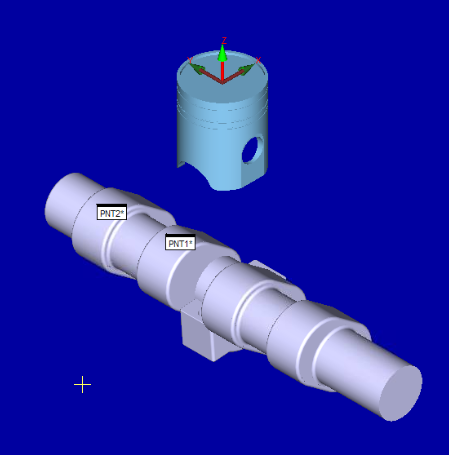
A CAD Assembly consists of two or more imported part models merged together in the Graphic Display window. For example, the graphic below shows an assembly of two visible parts.
A Sample CAD Assembly
You can have multiple parts and even multiple assemblies together in a single .cad file.
To work with assemblies, open the CAD
Assembly dialog box. From the CAD toolbar,
select the Assembly icon  , or select Edit
| Graphic Display Window | CAD Assembly.
, or select Edit
| Graphic Display Window | CAD Assembly.
CAD Assembly dialog box
The CAD Assembly dialog box contains a list of all imported and merged parts, assemblies, and CAD section cuts used in the Graphic Display window. You can use this dialog box to view, edit, and manage assemblies of parts. You can also resize this dialog box, and the software remembers the last used size and position the next time it opens.
This dialog box contains these options:
Information Box
The gray box at the top of the dialog box displays information about the item currently selected on the Assembly Tree View. The information changes depending on the item selected.
Assembly Tree View
The left side of the dialog box has a tree view that represents the CAD assembly structure. Each item in the tree view represents an assembly component.
If you select a component from the tree view, PC-DMIS displays information about that item in the gray box above the list.
If you double-click a component in the assembly, PC-DMIS selects and highlights the component in the Graphic Display window. Conversely, with the CAD Assembly dialog box open, if you press and hold the Alt key and then left-click a CAD object in the Graphic Display window, PC-DMIS selects its corresponding component in the tree view. This helps to identify which CAD objects belong to which assembly component.
Each component has its own check box to show or hide that component immediately within the Graphic Display window.
If you mark a check box, PC-DMIS shows that component.
If you clear a check box, PC-DMIS hides that component (and any children components, regardless of their visibility state).
Once you mark a check box, you can use the buttons in the Visibility area to change the visibility state of that component or of its sibling or children components.
Your original imported image name has the number 1 appended to its name. Any CAD transformation that creates a new instance of this same CAD file are then incremented to have a unique number. See "Transforming a CAD Model".
Mirrored CAD File names with unique numbers inside a CAD Assembly Tree View
For information on SectionCutCurve entries, see "Creating and Viewing Section Cut Curves".
A shortcut menu appears when you right-click in the tree view. The shortcut menu contains these items:
Select - This item functions as if you had double-clicked on the assembly component.
Unselect - This item deselects the assembly component in the Graphic Display window.
Expand Descendants - This item expands an assembly to show a list of child parts making up the assembly.
Hide - This item hides the selected component.
Hide Siblings - This item hides all of the components except the selected component at the same level on the assembly tree.
Show - This item shows the selected component.
Show Siblings - This item shows all of the components except the selected component at the same level on the assembly tree.
Show All - This item shows all the components on the assembly tree.
Rename - This item renames the selected component in the assembly.
Delete - This item deletes the selected component from the assembly and removes it from the Graphic Display window. You cannot delete the root tree view component.
Transform - This item displays the CAD Transform dialog box. This dialog box allows you to transform (translate, scale, and rotate) a single component in the assembly. You cannot transform the root tree view component. For more information, see "Transforming a CAD Model".
Coordinate System - This item displays the CAD Coordinate System dialog box. This dialog box lets you create and manage different coordinate systems. For more information, see "Working with CAD Coordinate Systems".
Replace Component - This item allows the selected assembly component to be replaced with another CAD model. This model can either be an imported CAD model or a model connected with the DCI. The submenus have the same structure as the File | Import and File | Direct CAD Interface menu options respectively. The new model replaces whatever model is associated with the selected node. The new model on the node retains any transformation that was applied to the previous model. For information on how to import model files, see "Importing CAD Data or Feature Data" in the "Using Advanced File Options" chapter.
Visibility
The Visibility area provides option buttons and icon buttons that allow you to run visibility operations in order to change the hidden state of assembly component groups.
 The colored icon at the top
of this area shows your current screen layout. It corresponds with the
icon used in the Layout area of the View
Setup dialog box. See "Setting
Up the Screen View".
The colored icon at the top
of this area shows your current screen layout. It corresponds with the
icon used in the Layout area of the View
Setup dialog box. See "Setting
Up the Screen View".
The Blue, Red, Yellow, and Green options limit the visibility operation to only that "view" of the Graphic Display window. The All option applies the visibility operation to all views.
These command buttons have pictures on them that depict their action:
 Hide - This button hides the selected component.
 Hide Siblings - This button hides all of the components except
the selected component at the same level on the assembly tree.
Hide Siblings - This button hides all of the components except
the selected component at the same level on the assembly tree.
 Show - This button shows the selected component.
 Show Siblings - This button shows all of the components except
the selected component at the same level on the assembly tree.
Show Siblings - This button shows all of the components except
the selected component at the same level on the assembly tree.
 Show All - This button shows all the components on the assembly
tree.
Show All - This button shows all the components on the assembly
tree.
Only the hide and show properties are applied to individual views. The Color and Transparency settings in the Editing area are always applied to all views.
Editing
The Editing area lets you edit the currently selected component from the Assembly Tree View.
Create Assembly - This button
creates a new assembly node in the currently selected assembly. Initially,
the node is empty, but you can then move other assembly components into
it by using the up and down arrow buttons (
 )
on those components.
)
on those components.
Create Part - This button creates a new part node in the currently selected assembly. Initially, the node is empty, but you can move CAD objects into it by using the Move to Part button in the CAD Elements area.
Up Arrow -
This button moves the part or assembly component in the tree view up into
the assembly just above it in the list.
Down Arrow -
This button moves the part or assembly component in the tree view down
into the assembly just below it in the list.
Color - This check box enables the Color button and displays the Color dialog box. This dialog box lets you apply a color to the selected tree view component. This check box also enables or disables the display of the selected color. Once you choose the initial color, you can click the Color button thereafter to modify the color used. This overrides any colors set for CAD elements using the Edit CAD Elements dialog box until the assembly component no longer uses a color or is removed from the CAD Assembly dialog box. For more information, see "Editing CAD".
Level - This list lets you assign the CAD objects within the selected assembly component to a predefined CAD level. This action overrides any CAD level assignments that were set using the CAD Levels dialog box until the assembly component is removed from the level or from the assembly within the CAD Assembly dialog box. For more information, see "Working with CAD Levels".
Transparency - This check box applies the selected transparency percentage to the selected tree view component. You can drag the slider or change the value manually in the box to change the transparency percentage.
You cannot perform some edit operations on the root-level component (usually the part name used in your measurement routine) or DCI components. Those operations that you cannot use are disabled when you select these types of components.
Save Views
The Saved Views area lets you manage different visibility states of the Assembly Tree View.
Save - This button saves the current visibility state, giving it the name specified in the current Saved Views box. You must click the OK button to permanently save your view. PC-DMIS stores saved views in the .cad file associated with the measurement routine.
Delete - This button deletes the stored visibility state of the name selected from the Saved Views box.
To load a stored visibility state, select it from the Saved Views list. The check boxes in the Assembly Tree View are immediately modified according to the loaded view.
CAD Elements
The CAD Elements area lets you select CAD objects and move them to a different part. You can select or deselect CAD objects within the Graphic Display window. To do that, click on them individually, or for multiple CAD objects, drag a box around them.
Move To Part - This button moves the selected CAD objects to the currently selected part in the Assembly Tree View.
Deselect All - This button deselects all previously selected CAD objects.
Selection Filter - This area lets you filter the CAD objects that PC-DMIS can select. If an item is selected, PC-DMIS has the ability to select that type of CAD object when you click or box-select CAD objects in the Graphic Display window.
You can also filter the selection by the color of the CAD object. If you select the Color check box, the color of the next CAD object that you select in the Graphic Display window is then used as the filter color. For subsequent selections, you can only select CAD elements with that color.
More: