PC-DMIS lets you work with CAD GD&T callouts that are part of your CAD model in the Graphic Display window. You can show and hide these callouts, reposition them, change their view options, filter them, and import them into your measurement routine.
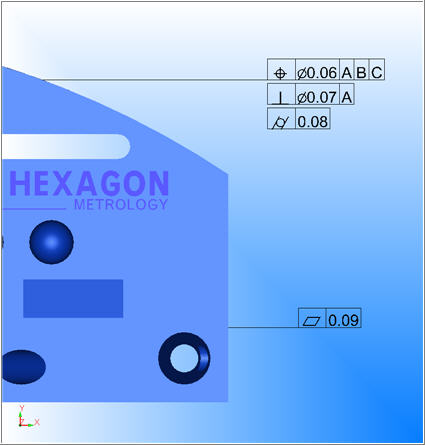
Sample CAD GD&T Callouts Displayed in the Graphic Display window
These CAD GD&T callouts are not Feature Control Frame (FCF) dimensions. CAD callouts instead reside directly in your CAD model and appear as CAD elements. They do not initially perform any function inside of PC-DMIS other than providing visual information in the Graphic Display window. However, you can import them as GD&T FCF dimensions into your measurement routine. For information on how to do this, see "Importing CAD GD&T Callouts" below.
To work with CAD GD&T callouts, your license must include the CAD and GD&T Selection options, or CAD++. Also, your CAD model must use a supported format. Supported formats include: CATIA v5, CATIA v6, Creo, NX, SolidWorks, and STEP AP242.
PC-DMIS also partially supports CAD GD&T callouts in IGES files. The IGES file must contain the following:
During the import process, PC-DMIS attempts to match the 2D GD&T callouts to the 3D features on the IGES model. Once PC-DMIS matches 2D callouts to the 3D features, you can then import the embedded callouts as features and FCF dimensions.

 Showing
or Hiding CAD GD&T Callouts
Showing
or Hiding CAD GD&T Callouts
To show and hide the
callouts, from the Graphic Items toolbar,
click the Show
GD&T icon ( ).
If you want the callouts to always appear in newly created measurement routines,
from the PC-DMIS
Settings Editor, in the Options section,
set the ShowCADGDT entry to TRUE.
).
If you want the callouts to always appear in newly created measurement routines,
from the PC-DMIS
Settings Editor, in the Options section,
set the ShowCADGDT entry to TRUE.
Showing
or Hiding CAD GD&T Notes
To show or hide GD&T notes, from
the Graphic Items toolbar, click the Show
GD&T Notes icon ( ).
).
GD&T notes contain information embedded directly within the CAD model.
You cannot import them as commands into the Edit window.
Showing
or Hiding CAD GD&T Characteristic IDs
You can use the Characteristic IDs icon ( )
on the Graphic Items toolbar to show and
hide CAD GD&T characteristic IDs on CAD GD&T callouts. A characteristic
ID on a callout is a unique identifier assigned to the CAD GD&T
by the native CAD software. You can only see a characteristic ID if
its corresponding CAD GD&T is also visible.
)
on the Graphic Items toolbar to show and
hide CAD GD&T characteristic IDs on CAD GD&T callouts. A characteristic
ID on a callout is a unique identifier assigned to the CAD GD&T
by the native CAD software. You can only see a characteristic ID if
its corresponding CAD GD&T is also visible.
For information on the Characteristic IDs icon on the Graphic Items toolbar, see "Graphic Items Toolbar" in the "Using Toolbars" chapter of the PC-DMIS Core documentation.

Example of Characteristic IDs
You can modify the font size with the Graphic Font on the Font Setup dialog box. The font Color on that dialog box controls the background color of the characteristic ID. The foreground color automatically uses black or white to maintain good contrast.
For information on the Font Setup dialog box, see "Customizing User Interface Fonts" in the "Setting Your Preferences" chapter.
You can use an Excel sheet to map different values to each characteristic ID and show those instead. To do this, use the Balloon ID tab on the CAD and Graphic Setup dialog box.
For information on the Balloon ID tab, see the "Balloon ID Tab" topic.
Don't confuse these characteristic IDs with the characteristic IDs PC-DMIS uses when you import a CAD GD&T callout. That type of characteristic ID comes from the native CAD model's PMI. For additional information on characteristic IDs in feature names, see "Use Characteristic ID Naming" in the "Setting Your Preferences" chapter.
Viewing
Associated CAD Elements
If you have the CAD Information dialog box open (View | CAD Information) and you click on a CAD GD&T callout, the software highlights the associated CAD element.
Inside the CAD Information dialog box, you can then click on links inside of curly braces to zoom in on specific CAD elements.
For more information on the CAD Information dialog box, see "Viewing CAD Information".
Another way to view associated CAD elements is to press Shift and position your mouse pointer over the GD&T callout. PC-DMIS highlights both the callout and all CAD elements linked to the callout:

Example of highlighting the surface for datum C
Associating
CAD GD&T Callouts with CAD Elements
When you import a part with embedded CAD GD&T callouts, PC-DMIS does it's best to link it to the correct CAD element. If PC-DMIS links something incorrectly, you can fix it with the Associate CAD elements shortcut menu.
To access this menu, from the Graphic
Modes toolbar, click the GD&T Selection Mode (from CAD) button
( ). Then right-click
on a CAD GD&T callout and choose Associate
CAD Elements to open the Associate
CAD Elements dialog box.
). Then right-click
on a CAD GD&T callout and choose Associate
CAD Elements to open the Associate
CAD Elements dialog box.
This dialog box shows the current associated CAD elements in the Elements list:
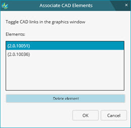
Associate CAD Elements dialog box with two associated elements
You can click on any element to zoom to that element in the Graphic Display window.
Select the Associate CAD elements shortcut menu to see the current association in the Associate CAD Elements dialog box.
From the Elements list, select the element.
Click the Delete element button to remove the item from the Elements list.
Click OK to confirm the change.
Choose the Associate CAD elements shortcut menu to see the current association in the Associate CAD Elements dialog box.
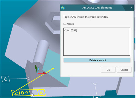
GD&T callout initially associated to a single element
With the dialog box open, from the CAD model, click on a CAD element. PC-DMIS highlights the selected CAD element and adds it into the Elements list.
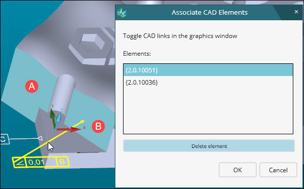
GD&T callout now associated to both elements (A and B)
Click OK to confirm the change.
Associating
CAD GD&T Callouts with Existing PC-DMIS Features
Similar to creating and removing associations between GD&T callouts and CAD elements, you can also add or remove an association between CAD GD&T callouts and existing features from your measurement routine. This can be helpful if you do not want to use the default Auto Feature method to measure a feature. For example, you may want to create constructions instead.
To associate a CAD GD&T callout with an existing PC-DMIS feature, do this:
From the Graphic
Modes toolbar, click the GD&T
Selection Mode (from CAD) button ().
From the CAD Setup toolbar (View | Toolbars | CAD Setup), select the view associated with the features from the CAD Model View list. The view you select must have the PMI and displayed as shown.
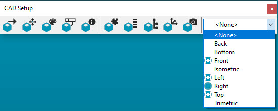
Example of view options with PMI in CAD and displayed (Front, Left, Right, and Top)
Right-click on a CAD GD&T callout in the Graphic Display window and select the Associate Feature(s) option.
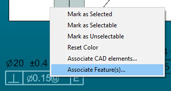
PMI menu with the Associate Feature(s) option selected
The Feature/CAD Association dialog box opens. Select a feature from the Features list on the left to view its associated CAD feature elements in the Associated CAD element(s) list on the right. PC-DMIS highlights all associated feature elements in the Graphic Display window.
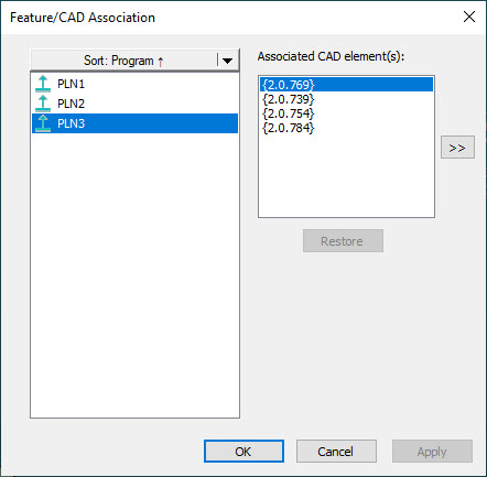
Feature/CAD Association dialog box
Click OK to save your changes.
To remove an association between a CAD GD&T Callout and a feature, do this:
Right-click on a CAD GD&T callout in the Graphic Display window and select the Associate Feature(s) option.
Select a feature from the Feature list on the left to view the associated feature elements in the Associated CAD element(s) list on the right. PC-DMIS highlights all the elements associated with the selected feature on the CAD model in the Graphic Display window.
Click any of the highlighted features in the Graphic Display window to temporarily remove them from the Associated CAD element(s) list. This also removes their association with the selected feature in the Feature list causing PC-DMIS to no longer highlight the selected feature in the Graphic Display window.
You can also select the feature element from the Associated CAD element(s) list and click the >> button to remove the association.
Click the Restore button to insert the feature element back into the Associated CAD element(s) list. This restores its association with the selected feature and PC-DMIS highlights the element in the Graphic Display window again.
Click OK to save any changes you made.
Once you click OK, any associations you removed are permanent. If you need to recreate the association, you must perform the steps to associate a CAD GD&T callout with a CAD feature and select the feature element that you removed.
Once you associate a feature with a CAD surface, PC-DMIS recognizes it when it consumes the GD&T callout and uses the pre-existing, associated feature rather than inserting a new feature into the measurement routine.
To reposition a CAD
GD&T callout, from the Graphic Modes
toolbar, turn on Text Box mode ( ), and then drag the callout to
a new location.
), and then drag the callout to
a new location.
From the Graphic
Modes toolbar, turn on Text
Box mode ().
Right-click on a GD&T callout, and from the shortcut menu, select CAD GD&T Display Filter to show the CAD GD&T Display Filter dialog box. This dialog box shows a list of CAD GD&T information and two columns of option buttons (Show all and Hide all).
For each item you want to show or hide, click Show all or Hide all to immediately toggle the visibility state of that GD&T callout.
Click OK to close the dialog box and store the current filtered state until accessed and modified later.
Showing
or Hiding Individual Callouts
From the Graphic
Modes toolbar, turn on Text Box
mode (), right-click
on a GD&T callout, and select one of the Show or Hide ID menu
items.
PC-DMIS can import selected GD&T callouts as dynamically-generated FCF dimensions or datum definitions.
From the Graphic Items toolbar, click the Show GD&T
icon (), to ensure
that the GD&T callouts are visible.
You can hide all the label
types, so that they don't fill up the screen during the import process.
To do this, from the Graphic Items toolbar,
click the Show All Label IDs icon ( ).
).
Do one of the following:
Select Operation | Graphic Display Window | GD&T Selection | Select All GD&T. This option selects all embedded CAD GD&T callouts and converts them into Edit window commands.
Select Operation | Graphic Display Window | GD&T Selection | Select GD&T in Current View. This option selects only the embedded CAD GD&T callouts that are visible and converts them into Edit window commands.
Select Operation | Graphic Display Window | GD&T Selection | Select GD&T in Active CAD Model View. This option creates GD&T dimensions from the embedded CAD GD&T callouts stored inside an active CAD model view. This menu remains grayed out until you make a view active. To make a view active, from the CAD Model Views dialog box (Edit | Graphic Display window | CAD Model Views), from the list of views, double-click on a model view. For information on CAD Model Views, see "Working with CAD Model Views".
Enable the GD&T
Selection Mode (from CAD) () icon
on the Graphic Modes toolbar. Then click on a single item. In the Edit window,
PC-DMIS
generates all necessary commands that make up the specific datum
definition or FCF dimension. These commands are temporary. PC-DMIS removes them
if you click Cancel. From the Geometric Tolerance Command dialog box that
appears, make any changes to the FCF dimension. Click OK
to accept the dimension and make referenced temporary commands
permanent. Temporary commands that are not referenced are removed.
Even if PC-DMIS is not in GD&T Selection Mode (from CAD), as long as PC-DMIS is in a supported mode and the callout is visible, you can press Shift and click on the callout to import it. Supported modes include Translate mode, 2D Rotation mode, and 3D Rotation mode.
Enable the GD&T
Selection Mode (from CAD) () icon
on the Graphic Modes toolbar. Then box-select multiple callouts. In the Edit
window, PC-DMIS
generates all necessary commands that make up the selected datum
definitions or FCF dimensions.
If the selected CAD GD&T callouts don't have geometry features, they are incomplete. You cannot import incomplete GD&T callouts into the measurement routine. PC-DMIS shows incomplete or invalid callouts in the Invalid GD&T tab of the CAD GD&T Selection Information dialog box.
If you hold down Shift
before you click on or box-select the CAD GD&T callout item, the
software generates the FCF datum definitions and commands in the Edit
window without showing the Geometric Tolerance
Command dialog box.
By default, if you hold down Shift and click
(or double-click) on a GD&T callout item, PC-DMIS displays the
measurement strategy widget. You can use this widget to change a feature's
main parameters. For more information on this widget, see "Using
the Measurement Strategy Widget" in the "Creating
Auto Features" chapter.
You can import a rectangular and circular datum target areas if they are aligned to an axis. The following picture shows some sample datum target areas:

The left shows a circular area, while the right sample shows rectangular area
When you import a datum target area, the software creates the following in the Edit window:
A High Point feature
A workplane that corresponds to the target area surface normal
When you import callouts, you can have the features use their native characteristic IDs instead of PC-DMIS's default feature naming. For more information see "Use Characteristic ID Naming" in the "Setting Your Preferences" chapter.
The Operation | Graphic Display Window | GD&T Selection | View Invalid GD&T for Selection menu option opens the Invalid GD&T tab on the CAD GD&T Selection Information dialog box. This tab also appears after you import CAD GD&T callouts as Edit window commands and some callouts were incomplete or invalid.
This tab analyzes all the CAD GD&T callouts to locate invalid callouts. Invalid callouts are those that the software cannot solve for selection. The dialog box then displays these callouts in a list.
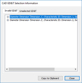
CAD GD&T Selection Information dialog box - Invalid GD&T tab
You can expand an object to see a description of why the software cannot solve the object for selection.
You can click on an object to highlight the object in the Graphic Display window. You can double-click on an object to highlight and scale the object. These make it easier to locate.
The Copy to clipboard button copies the text of the contents to the Clipboard.
This option cannot detect all the reasons why the software cannot solve an object for selection. This means objects may not appear in this dialog box that it cannot solve.
Viewing
Unselected GD&T Callouts
The Operation | Graphic Display Window | GD&T Selection | View GD&T Not Selected menu option opens the Unselected GD&T tab on the CAD GD&T Selection Information dialog box.
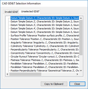
CAD GD&T Selection Information dialog box - Unselected GD&T tab
This tab analyzes all the CAD GD&T callouts to locate unselected callouts. Unselected callouts are those that you have not selected using GD&T selection. That is, these callouts don't have corresponding measurement routine commands.
Once you import them with GD&T selection, they no longer appear in this tab. For information on GD&T selection, see the "Importing CAD GD&T Callouts" subtopic above.
You can click on an object to highlight the object in the Graphic Display window. You can double-click on an object to highlight and scale the object. These make it easier to locate.
The Copy to clipboard button copies the text of the contents to the Clipboard.
Setting
CAD GD&T Callout Colors
You can set the colors the software uses for valid and invalid CAD GD&T callouts in the Graphic Display window. For information on how to do this, see "CAD GD&T Tab" under "Setting Up CAD and Graphics".
Marking
CAD GD&T Callouts with Colors for Selected, Selectable, or Unselectable
You can set CAD GD&T Callouts to different colors to better communicate the state of the current callout (selected, selectable, or unselectable).
For more information, see "CAD GD&T Callouts Shortcut Menu" in the "Using Shortcut Keys and Shortcut Menus" appendix.
You can use .exclude files to exclude items that PC-DMIS would normally accept as selectable CAD GD&T callouts. One reason to do this is to only display callouts that apply to a specific measurement device.
Choose Edit | Graphic Display Window | CAD GD&T to access the CAD GD&T tab on the CAD and Graphic Setup dialog box.
From the Exclude area, click Generate to create an .exclude file based on the available CAD GD&T callouts.
Click Edit to open the .exclude file in a text editor.
For any item that you want to exclude, remove the single quote character at the front of the line.
Mark the Use exclude file check box.
In the Exclude area, click Apply if you want to color the excluded CAD GD&T callouts.
Click Hide excluded data, if you want to hide the items you chose to exclude.
Click OK.
For information on .exclude files, see the "CAD GD&T Tab" topic in this chapter.
Instead of using the Generate button to create the .exclude file, you can also manually create your own .exclude file. To do this:
Create a text file with the same name as your measurement routine. Give the text file the .exclude filename extension.
Use a text editor, and type the Characteristic IDs to exclude on separate lines. You only need to type the IDs. If an ID has a space in it, put quotes around the ID. For example, an ID of A 1 should be "A 1".
Save your changes, and place the .exclude file in the same directory as the measurement routine.
Related Topics: