Step 10 - Review the Calibration Results
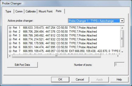
When the calibration of the ACR1 Probe Changer is complete, select the Ports tab in the Probe Changer dialog box (Edit | Preferences | Probe Changer). This tab displays the calibration information for the location of each calibrated port. For example:
Probe Changer dialog box - Ports tab with calibration results
When you view the results, look for the following. Any significant deviations from these expectations may be due to a bad hit.
The position and spacing of the ports. For example, the ACR1 rack defined in this calibration process is aligned parallel to the Y axis of the CMM.
The X values of the ports should be, within reason, nearly identical since all of the ports are co-linear.
Similarly, the Z values should also be nearly identical, since the ports are all at the same height.
The Y values should be equally spaced (roughly 35 mm apart).
The results during measurement routine execution are:
During measurement routine execution, probe entities that are added to each of the ports are automatically picked up from that location whenever PC-DMIS executes a LOADPROBE command for that probe.
The probe body moves to the mount point and then into the port, which pushes the lid backwards.
The key mechanism automatically turns to disengage/engage, loads the new module, and continues to measure.