Step 2 - Define the Communications Port
You can use the ACR1 Probe Changer in one of two modes:
Host mode - In this mode, the rack controller connects to a communications port on the computer via a cable. All of the functions are based on signals between the two devices. The probe changer needs to connect to a serial communications port if you use it in host mode. You need to identify this communications (Comm) port before calibration can begin.
If you use host mode, follow the steps below.
Stand-alone mode - In this mode, there is no direct communications with the computer or PC-DMIS. This means that all rack functions are based on timing. The probe changer relies on timing to do a change cycle (to deposit and collect hardware from the probe changer). Respective modes are configured with the dip switched on the rear of the rack controller(s). They are covered in the Renishaw documentation or in the prints for the specific CMM configuration and are not covered here.
If you use stand-alone mode, skip to "Step 3 - Define the Mount Point".
To define the communications port:
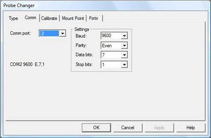
Select the Comm tab in the Probe Changer dialog box (Edit | Preferences | Probe Changer).
In the Comm port box, select port 2 (typically if you use Host mode) or None (if you use Stand-alone mode). The setting depends on the machine’s configuration.
Probe Changer dialog box - Comm tab
Unless otherwise indicated, use the following default settings:
Baud: 9600
Parity: Even
Data bits: 7
Stop bits: 1
Click Apply and then OK to close the dialog box.
Restart PC-DMIS to force the new port settings to be read. This step is very important. If you do not restart PC-DMIS, the system will not work properly when the port settings have been changed.
Once PC-DMIS restarts, select Edit | Preferences | Probe Changer to open the Probe Changer dialog box.
In the next step, you define the location of the probe body when you use the probe changer to switch probe components.