
When you select the Auto Wrist icon on the Auto Feature bar, PC-DMIS first proves if the current active tip can be used to measure the selected feature. If not, it determines the best wrist position (tip) to use when an Auto feature is measured. Upon feature creation, PC-DMIS displays the Auto Wrist dialog box in case a new tip is needed:
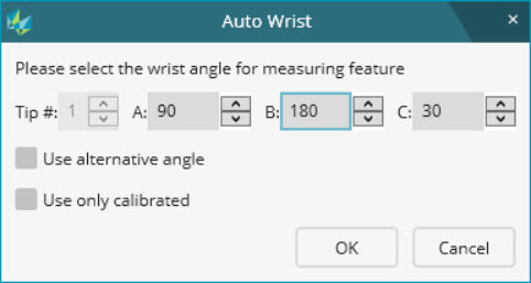
Auto Wrist dialog box
Use the options in the dialog box to specify the wrist angle that best approaches the feature:
Tip # box - This box represents the tip number. Typing or selecting a number in this box inserts the associated TIP command into the measurement routine.
A, B, and C boxes - These boxes define the A, B, and C angles for the wrist. Click the arrow to the right of each box to increment or decrement the respective angle to the next valid value.
Use alternative angle check box - If you want to avoid a possible collision during the probe rotation, select this check box.
Use only calibrated check box - If you want to only use existing calibrated tips, select this check box.
OK button - To insert the TIP command with the selected angles before the Auto feature, click this button.
Cancel button - To use the current wrist position to measure the feature, click this button.
When you directly measure a Laser Cone or Laser Cylinder with a Tesastar wrist, the best scanning direction may be along the feature’s vector or normal to it. This however depends on the ability of the head to rotate to an angle that allows you to scan in a direction normal to the stripe’s orientation. For details, see "Auto Cone Paths" or "Auto Cylinder Paths" in the PC-DMIS Laser documentation.
If you select the Auto Wrist icon, PC-DMIS chooses a position that most closely approximates the best approach direction:
For angle point features, the best approach direction is the average of the two surface vectors.
For corner point features, the best approach direction is the average of the three surface vectors.
For all other auto types, the best approach direction is the feature surface vector.
The Vector Point, Surface Point, Angle Point, Corner Point, Line, Edge, and Plane Auto Contact Features use the cone angle of 46 degrees. This is done to prevent a tip change in case the orientation of the current tip lies inside the acceptable cone.
The tip for the Line and Edge Auto Contact Features has to be inside of a half cone (46 degrees) specified by the edge vector.
If the icon is not selected, PC-DMIS uses the current wrist position to measure the feature.
More: