You can use the CAD select dialog box to create multiple Auto features at once. The CAD Select dialog box appears after you drag a box (box-select) on a CAD model. You must have the Auto Feature dialog box open to a supported feature type (for the supported feature types, see the "Box Selecting to Create Multiple Auto Features" topic), and you must box-select CAD elements of the feature type displayed in the dialog box. If you meet these conditions, the CAD select dialog box displays the number of selected CAD elements that match the selected Auto feature type.
For points or cylinder CAD elements, once the CAD Select dialog box opens, you can deselect and select highlighted elements if you click on them. For circle elements, however, once you deselect a circle, you cannot click on it again to re-select it.
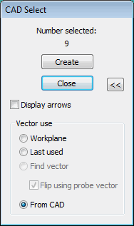
CAD Select dialog box
Create - This button creates Auto features of the selected type from the selected CAD elements (currently for points, circles, cylinders, or cones). PC-DMIS closes the CAD Select dialog box, and from each box-selected element, PC-DMIS generates the appropriate feature. The Vector use area in the advanced portion of the dialog box determines the vector method.
Close - Closes this dialog box and cancels the box selection.
>> or << - Shows or hides the advanced items on the dialog box. These advanced items control the features' vectors and are most often needed for imported DES models:
Display arrows - This check box displays or hides colored arrows showing the direction of vectors used by the methods in the Vector Use area.
The Vector use area lets you choose the methods PC-DMIS should use to determine the vectors for the nearly-created Auto features.
Workplane - This method uses the vector of the currently active workplane as the vector for each individual feature.
Last used - This method uses the last vector that was placed in the dialog box for the Auto feature. This lets you specify one vector to be used for all the selected features.
From CAD - This method uses the vector that is specified by the CAD feature. This method becomes available if vector data is available for each feature.
Find vector - This method finds the vector using the CAD surface data that is closest to the feature. This method is only available if surface data is available.
Flip using probe vector - During the CAD import process, some types of CAD (usually IGES) may have some surface normal vectors that incorrectly point into the part instead of out of the part. This method flips the selected features' vectors so that they point out of the surface, using the probe vector to help indicate the correct vector direction. That option becomes available when you box-select feature types that may have surfaces with incorrect normal vectors.