
Use the Path Definition tab for the Adaptive Free Form Plane Scan strategy to generate a scan path.
Type
The scan path can be generated by the following types of methods:
Points List Area
The points list area displays the points that you will select on the CAD or take on the CMM manually (for the teach path type only).
# - Displays a number or a letter that identifies the point.
X, Y, Z - The XYZ values appear in this area.
Pt. Type - This column indicates the type of point for the Teach Path method of generating the scan path.
To delete points, right-click in the points list area. The Remove and Clear options appear:

Points options
Remove - To delete one point, highlight it in the points list area, right-click, and then select this option.
Clear - To delete all points, right-click in the points list area and then select this option. When the Remove all points? message appears, click OK.
>>
To set additional properties for the type you selected and generate the scan path, click this button.
<<
To return to the points list area, click this button.
This method generates the scan path along the perimeter of the surface. It requires CAD.
Generating a Default Perimeter Scan Path
You can generate a default perimeter scan path for a given plane. The start point of the default path is the edge closest to the point (centroid) of the selected plane. The direction of the scan is counterclockwise in a given plane. The start and end points for scan are the same. The default path generation will use the parameter set in the second screen of definition of path generation. When you select Create, the Scan Path tab is filled up with the default path.
Selecting Multiple Surfaces of a Plane
A perimeter path supports planes that are separated.

Example of front face on demo block
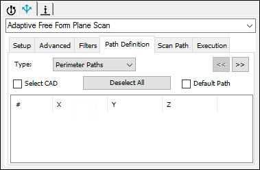
Path Definition tab
To select multiple surfaces of a plane:
Select the Select CAD check box.
If required, click Deselect All to deselect any selected surfaces.
Click on the first surface. PC-DMIS highlights the surface.
Click on the second surface. PC-DMIS highlights the surface.
If the first and second surfaces are separated, then PC-DMIS automatically selects the Default Path check box. The default path on each selected surface will be generated.
Select any more surfaces by clicking on them.
PC-DMIS completes the Scan Path tab when you select Create.
Generating a Perimeter Path by Selection
You can generate a perimeter path by selecting the start, direction, and end point on any one CAD surface, or by selecting the start and direction point on any one CAD surface to generate a closed scan path.
Do one of the following:
To define the start point, direction point, and end point, click on three points on the CAD. The points appear in the points list area. In the # column, 1 = start point, D = direction point, and 2 = end point.
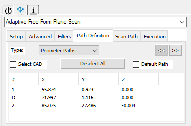
Sample Path Definition tab
To define the start point and direction point, click on two points on the CAD. The points appear in the points list area. In the # column, 1 = start point and D = direction point. When point 2 (the end point) is not defined, PC-DMIS uses point 1 to create a closed path.
If you need to edit a point, double-click the point. The Edit Point dialog box appears.
Edit Point dialog box
Change the values as required. To navigate to and modify points, click >>.
To set perimeter controls, click >>. The Perimeter Controls area appears. Use the properties in this area to control perimeter point generation.
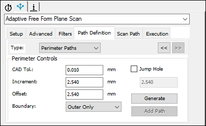
Sample Perimeter Controls area
CAD Tolerance - Type the tolerance that the point locating algorithm uses.
Increment - Type the minimum distance between adjacent points.
Offset - Type the offset distance from the boundaries.
Boundary Type - Select the boundary type on the selected surface that should be considered in the path calculation:
Inner Only - The inner boundaries are used to generate the scan path.
Inner or Outer - PC-DMIS determines whether the inner boundary or outer boundary should be used based on the hits taken, and generates hits.
Outer Only - The outer boundaries are used to generate the scan path.
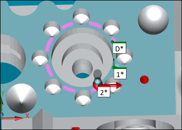
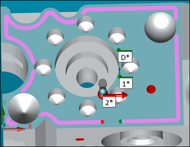
For example, suppose that points 1, D, and 2 are taken as shown below:
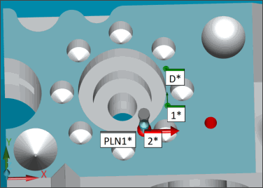
If Inner Only is selected, PC-DMIS generates the scan path as follows:
If Outer Only is selected, PC-DMIS generates the scan path as follows:
Jump Hole - If you select this check box, PC-DMIS generates a break point in the scan path whenever the scan path is over the holes in the CAD surface. Type the required distance from the edge in the box.
Generate - To generate the points and display them in the points list area, click this button. PC-DMIS shows the generated path on the CAD in the Graphic Display window. You can change the start point, direction point, and end point and then regenerate the scan path, if required.
Add Path - To add the points to the Scan Path tab, click this button.
This method generates the scan path along the path of the points defined. It requires CAD. To generate the scan path using this method:
Click on the CAD to define the free form path. A minimum of five points must be recorded to calculate the scan path. The points appear in the points list area.
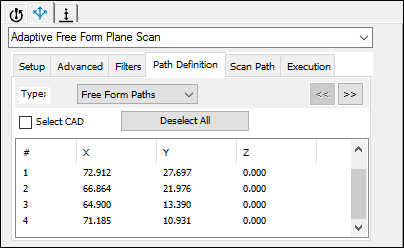
Sample Path Definition tab
The # column lists the number that identifies the point. To edit a point, double-click it. The Edit Point dialog box appears. Change the values as required. To navigate to and modify points, click >>.
To set free-form path controls, click >>. The FreeForm Controls area appears. Use the properties in this area to control free-form point generation:
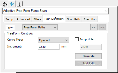
Sample FreeForm Controls area
Curve Type - Select the type of path to generate: open or closed.
Increment - Type the minimum distance between adjacent points.
Jump Hole - If you select this check box, PC-DMIS generates a break point in the scan path whenever the scan path is over the holes in the CAD surface. Type the required distance from the edge in the box.
Generate - To generate the points and display them in the points list area, click this button. PC-DMIS shows the generated path on the CAD in the Graphic Display window. You can change the points defining the free form path and then regenerate the scan path, if required.
Add Path - To add the points to the Scan Path tab, click this button.
You can generate this type of scan path by taking hits on the CMM or CAD to teach or learn the path. The scan path is made of lines, arcs, and/or circles.
For help with generating a teach path, refer to the example of a detailed procedure in the "Sample Teach Path for Adaptive Free Form Plane Scan Strategy" topic for scanning the top surface along a specific path.
To define the teach path:
Select the button for the type of path:
 Line
Line
 Arc
Arc
 Circle
For a line path, take one or two manual hits. For an arc path or a circle path, take two or three manual hits. The points appear in the points list area. For example:
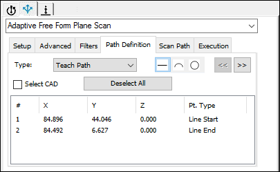
Sample Path Definition tab - Line path
The following items apply to the points list area:
The # column lists the number that identifies the point. The Pt. Type column describes the type of point, such as: Line Start, Line End, Circle End, or Circle Midpoint<number>.
Red points indicate that the path is incomplete. PC-DMIS does not use these points to generate the path. If you change the path type (for example, from a line to an arc), the red point(s) will be removed.
To edit a point's X, Y, and Z values, double-click the point. The Edit Point dialog box appears.
If you edit the start point or the end point of a circle path, both points will change because they are the same point.
To set teach controls, click >>. The Teach Controls area appears. Use the properties in this area to control point generation:
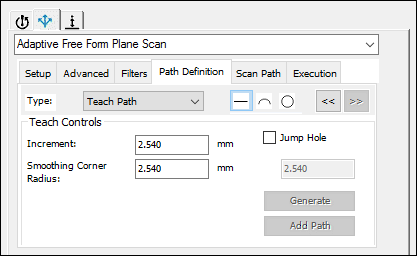
Sample Teach Controls area
Increment - Type the minimum distance between adjacent points.
Jump Hole - When you select this option, PC-DMIS generates a break point in the scan path whenever the scan path is over the holes in the CAD surface. Type the required distance from the edge in the box.
Smoothing Corner Radius - When PC-DMIS generates a scan path, the intersections will have sharp corners. A sharp corner requires the controller to slow down the scan speed. Smoothing the corner radius helps to smooth out the sharp corner. PC-DMIS defines the circle with the center as the intersection point, and the radius as entered in this box. PC-DMIS smooths out all of the points in the scan path found within this circle.
Generate - To generate the points and display them in the points list area, click this button. PC-DMIS shows the generated path on the CAD in the Graphic Display window. You can change the points that define the teach path and then regenerate the scan path, if required.
Add Path - To add the points to the Scan Path tab, click this button.