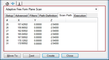
You can use the Scan Path tab for the Adaptive Free Form Plane Scan strategy to do the following:
Display scan points and move points
Import scan points and move points from a text file
Export scan points and move points to a text file
Insert a move point or break point
Following is an example:

Sample Scan Path tab
The following items appear in the points list area:
# - A number that identifies the generated point
X, Y, and Z - The XYZ values
When you click on any point in the scan path, PC-DMIS highlights the point on the CAD surface. For example:

Example of highlighted point on CAD surface
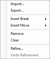
To perform additional functions, right-click in the points list area. The following options appear:

Points List options
Import
To import the scan points and move points from a text file, select this option. The path of the scan can be dynamically read from a text file when you run the measurement routine. This can help to scan the plane on variants of the part where the shape of the face being scanned is changed between variants.
Following is a sample of a partial text file:
-32.23,14.067,-0.001,SCAN
-29.2,6.684,-0.006,SCAN
-24.389,1.846,-0.008,SCAN
-19.309,-3.982,-0.004,SCAN
-15.327,-8.125,-0.004,SCAN
-9.949,-9.576,-0.004,SCAN
-4.838,-11.112,-0.001,SCAN
6.786,-10.431,-0.005,SCAN
12.121,-4.769,-0.003,SCAN
17.941,1.332,-0.005,SCAN
21.889,7.432,-0.002,SCAN
26.623,10.02,-0.004,SCAN
0,0,0,BREAK
27,10,50,MOVE
30.361,9.192,-0.003,SCAN
In this sample:
SCAN - Indicates a point that will be added to the scan.
BREAK - Indicates a move to the Retract, and then another scan will begin at the next SCAN point.
MOVE - Indicates a move to the location specified.
Export
To export the scan path to a text file, select this option.
Insert Break
To insert a break between scan points, select this option. As a result, PC-DMIS will send multiple scan commands to the controller. Break points in the scan path can help to scan a face as one single plane even if the path is not continuous due to any reason. The scan will do the following:
Retract off the part based on the current value for the Retract parameter.
Move to the next scan point at a prehit distance based on the current value for the Prehit parameter.
Begin the next scan.
Insert Move
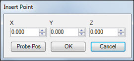
To insert a move point to avoid an obstacle, select this option. Move points in the scan path can help to scan a face as one single plane even if the path is not continuous due to any reason. The Insert Point dialog box appears:

Insert Point dialog box
You can position the probe and click Probe Pos to insert a move point at that location.
Remove
To delete one point, highlight it in the points list area, right-click, and then select this option.
Clear
To delete all points, right-click in the points list area and then select this option. When the "Remove all points?" message appears, click OK.
Refine
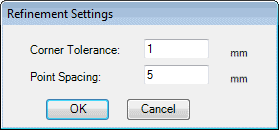
To vary the point density of the path based on the curvature of the path, select this option to display the Refinement Settings dialog box:

Refinement Settings dialog box
Corner Tolerance - The path regions with curvatures less than the value you type in this box will be converted into arc-segments.
Point Spacing - Type the maximum distance between adjacent points for linear portions of the path.
Undo Refinement
To undo the changes that you made in the Refinement Settings dialog box, select this option.