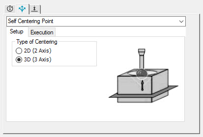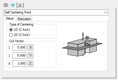
Use the Setup tab for the Self Centering Point strategy to select the type of self-centering point:

Sample Setup tab for 3D type
Type of Centering
Select the centering type:
2D (2 Axis) - To measure a 2D self-centering point, select this option and type the cut vectors. The cut vector is the vector of plane in which the point is measured. For example:

Sample Setup tab for 2D type
3D (3 Axis) - To measure a 3D self-centering point, select this option.
Using a Surface CAD Model to Create a 3D Self-Centering Point
You can create a 3D self-centering point from an internal cone, internal cylinder, or internal sphere.
Select the 3D (3 Axis) option. This message appears in the status bar:
"Please select a cone, sphere, or cylinder for 3D self centering."
Click on the internal cone, internal cylinder, or internal sphere.
The self-centering point depends upon the diameter of the current tip.
If it is feasible to use the current probe to self-center, PC-DMIS calculates a self-centering point and completes the X, Y, and Z boxes in the Vector Point Auto Feature dialog box with this point.
If it is not feasible to use the current probe to self-center, PC-DMIS calculates the center of the internal cone, internal cylinder, or internal sphere and completes the Vector Point Auto Feature dialog box with this point.
Using a Surface CAD Model to Create a 2D Self-Centering Point
Select the 2D (2 Axis) option. This message appears in the status bar:
"Please select a point on the first surface for 2D self centering."
Ensure that the values for the I, J, and K cut vectors are correct.
Click on the first surface.
Click on the second surface.
If it is feasible to use the current probe to self-center, PC-DMIS calculates a self-centering point and completes the X, Y, and Z boxes in the Vector Point Auto Feature dialog box with this point.
If PC-DMIS cannot locate the self-centering point, the message "2D self-centering calculations failed" appears in the status bar.
PC-DMIS takes the first point as the vector point and creates a plane perpendicular to that point. Similarly, PC-DMIS creates a second plane perpendicular to the second point. It then tries to calculate the self-centering point between the two planes. If the geometry of the part is different, this will only be an approximation. You can override the calculated value and type your own values.