When you perform a discrete hit calibration of a disk stylus on an analog probe with the qualification sphere, you need to use the Measure Probe dialog box and specify the following:
Five hits in the Number of Hits box
Two levels in the Number of Levels box
These do not apply for probes that use the Renishaw scan-based calibration.
Make sure that when you define your probe, you model a disk stylus and not a ball stylus. Once you click the Measure button in the Measure Probe dialog box, PC-DMIS automatically recognizes that you have an analog probe with a disk stylus and goes through this procedure:
If you moved the sphere, or if you chose the Man + DCC mode, PC-DMIS prompts you to take one manual hit on the very top of the qualification sphere (the north pole) with the center of the bottom of the disk stylus. If your probe configuration has an additional ball stylus attached to the bottom of the disk stylus, be sure to take the hit with that ball stylus.
If you didn't move the sphere, and you chose not to use Man + DCC mode, PC-DMIS takes the hit on the top of the qualification tool in DCC mode.
PC-DMIS uses the default value for these two entries when you build the disk probe:
The entries no longer affect the probe once it is built. The values used when you calibrate the probe are stored inside the probe itself. You can change these two values from the Probe Utilities dialog box.
To do this, follow these steps:
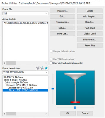
Open the Probe Utilities dialog box (Insert | Hardware Definition | Probe).
Probe Utilities dialog box for a disc stylus
Double-click the disk tip component (shown highlighted in the image above) to display the Edit Probe Component dialog box.
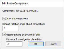
Edit Probe Component dialog box for a disk stylus
For the Measure plane on bottom of disk check box:
When selected (ProbeQualAnalogDiskUsePlaneOnBottom entry set to 1), PC-DMIS takes four hits on top of the sphere using a circular pattern on the bottom of the disk stylus and calculates a plane from it. Measuring a plane helps ensure that the hits for calibrating the face are oriented properly to reflect the actual plane of the disk. This is the default for the traditional calibration method using discrete hits.
When not selected (ProbeQualAnalogDiskUsePlaneOnBottom entry set to 0), PC-DMIS does not attempt to measure a plane on the bottom of the disk's face. Instead, it uses the design orientation of the disk. This is the default for the Renishaw scan-based calibration.
You can type in a value in the Distance from edge for plane hits box (ProbeQualAnalogDiskBottomHitsDistanceFromEdge entry). You can use it to affect the location of the hits on the bottom of the disk stylus during calibration.
PC-DMIS then finishes by doing the following in DCC mode:
After the hits are taken on top of the sphere, it takes six hits on two levels to get a close location of the center point of the sphere.
It uses the center point along with the vector from either the plane measurement or the design orientation to correctly position the subsequent measurement.
For discrete hit calibration, it takes five hits (four in a circular pattern around the equator of the sphere and the fifth hit on the top, or the pole, of the sphere).
For scan-based calibration, it takes a series of scans at two different levels (one slightly below the equator and one slightly above the equator). Each level is scanned in both clockwise and counterclockwise directions. Each direction for each level is also scanned using two different scan force offsets. This results in a total of eight scans.
PC-DMIS also provides the ProbeQualAnalogDiskPlaneStartAngle entry in the PC-DMIS Settings Editor in the ProbeCal section. This is another entry that you can use to affect the location of the hits on the bottom of the disk stylus during calibration.
For more information on any of the entries discussed here, see the "ProbeCal" section of the PC-DMIS Settings Editor documentation.