Step 9: Create an Alignment
This procedure sets the coordinate system's origin
and defines the X, Y, and Z axes. For information about alignments, see
the "Creating
and Using Alignments" chapter in the PC-DMIS Core documentation.
Throughout this process,
pay attention to the trihedron symbol in the Graphic Display window.
When you first open the Alignment Utilities
dialog box, it begins to slowly move about somewhat.

This indicates that
you have not finished the alignment and that there are still some
degrees of freedom.
Select Insert | Alignment
| New to open the Alignment Utilities
dialog box.
Throughout this process, ensure that the Auto check box remains marked. This moves the
axes based on the feature type and the orientation of that feature.
In the dialog box, from the list of features,
select the plane feature ID (PLN1).
Click the Level button
to establish the orientation of the normal axis of the current working
plane.
Select the plane feature ID (PLN1)
a second time.
Click the Origin
button. This action translates (or moves) the part origin to a specific
location (in this case, on the plane).
Select the line feature ID (LIN1).
Make sure Rotate to
is set to XPLUS. Make sure About
is set to ZPLUS.
Click the Rotate
button. This action rotates the defined axis of the workplane to the
feature. PC-DMIS rotates the defined axis around the centroid that
is used as the origin.
Select the circle feature ID (CIR1).
Click the Origin
button. This action moves the origin to the center of the circle and
keeps it at the level of the plane. You can see that the trihedron
moves in both the Z+ and Y- views and is fixed in place. This indicates
the position of the new alignment.
At this point, the Alignment Utilities
dialog box and Graphic Display window should look similar to what's here:
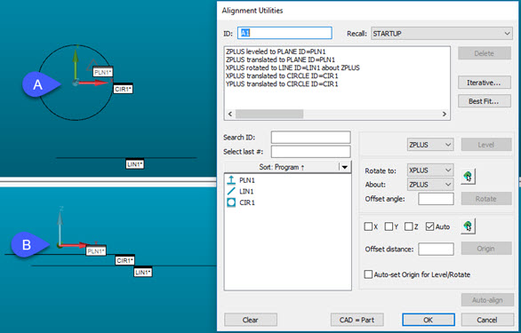
At left - Graphic Display window with trihedron in A)
Z+ view and B) Y- view
At right - Alignment Utilities dialog box with the current
alignment
When you complete the above steps, click OK
to insert the alignment into the Edit window:
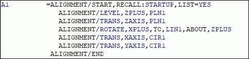
Edit window with the new alignment
An alignment command defines the alignment for the
feature commands that are below it in the Edit window.
If your cursor is at or below the A1 alignment, then
on the Settings toolbar, the Alignments
list shows A1, the name of the new alignment.
You can also use the 321Alignment
( )
button on the Wizards toolbar to access the
PC-DMIS 3-2-1 Alignment Wizard.
)
button on the Wizards toolbar to access the
PC-DMIS 3-2-1 Alignment Wizard.
Go
to the next step: "Set Preferences"