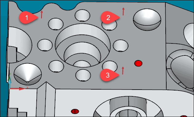
First, you need to select a plane feature. To do this, you need to take three or more hits on the top surface of the CAD model. This example uses three hits.

Red arrow bases show three hit locations on the part's surface
Before you take hits, verify that PC-DMIS is
set to Program Mode. To do this, from the
Graphic Modes toolbar, select the Program Mode button ( ).
).
In the Graphic Display window, in the top view, click on the top surface of the part to register a hit. This is the first hit.
Take at least three hits on the top surface, similar to the image above.
The hits must form an imaginary well-formed triangle or area.
The hits need to be well spread out.
As you take hits, PC-DMIS stores them inside of a hit buffer. If you take a bad hit, press Alt + - (minus) on your keyboard to delete it from the hit buffer. You can then retake the hit.
After the final hit, press the End key to create a plane feature from the hits.
PC-DMIS displays a feature ID (PLN1) and a triangle in the Graphic Display window. The triangle in the Graphic Display window indicates your measured plane feature.
The images below, and the other images for the other alignment features intentionally do not show the CAD model. This is so you can more easily see what PC-DMIS inserts into the Graphic Display window when you create these features.

A - Plane feature in the Z+ view
B - Plane feature in Y- view
PC-DMIS also inserts a FEAT/PLANE command in the Edit window.