It's always a good idea to test for collisions when you're about to execute commands in DCC mode. This can help prevent hardware damage.
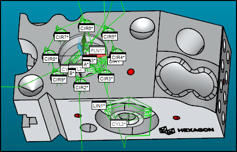
This step in the tutorial turns on path lines so that you can see the probe route and test for any collisions before you execute the routine and measure the part with your hardware.
Select Operation | Graphics Display Window | Collision Detection to open the Collision Detection dialog box. PC-DMIS also shows green path lines in the Graphic Display window. These lines represent the path the probe takes during execution.

From the Collision Detection
dialog box, turn on Stop on Collision ( ).
).
For each of the manual hits for your alignment
features, click Continue ( ) to simulate the probed
hits on those features.
After your final manual hit, DCC mode takes over, and the probe in the Graphics Display window follows the path lines. The Collision List dialog box shows any collisions. Path lines with collisions turn red. If something turns red, access the Collision List dialog box and resolve the collision (see the sub-topics below). If you don't see the list of collisions, it may be behind the Collision Detection dialog box.
Collisions may occur because of the probe's location
before you even begin to execute a routine. For example, a final manual
hit on a manual feature or the final measurement on an earlier execution
may have the probe in a position that could cause a collision later.
Always be aware of where the probe is before you begin to execute something
in DCC mode, and move it to a safe location at beginning of a new execution.
If the Collisions List dialog box shows "Basic Hit", you can ignore that collision. In this tutorial, those are manual hits, and you'll be moving the probe manually to those locations.
Resolving Collisions between Features
To resolve collisions between features, you can add MOVE/POINT or MOVE/CLEARPLANE commands into the Edit window to move to a specific point or plane. You can also add MOVE/POINT commands on path lines between features. For more information, see "Moving Path Lines" in the "Editing the CAD Display" chapter of the PC-DMIS Core documentation.
Resolving Collisions in a Feature
To resolve collisions for hits inside a single feature, you likely need to adjust some feature settings. For example, the cylinder Auto features in this tutorial (CYL1, CYL2, CYL3, and CYL4) have Depth or Ending Offset values that may cause the probe to contact with material near the bottom or end of the cylinder.
To fix this, you may need to press F9 on each affected feature and change the Depth or Ending Offset. For more information, see "Adjust Feature Values".
Go to the next step: "Adjust Feature Values"