Quick Start Align toolbar
The Align toolbar is used to create alignments from specific feature types by using these procedures.
Icon |
Description |
Quick Start Procedure |
 |
Plane, Line, Line alignment |
Select or measure a Plane to level to, and click Next. Select or measure a Line to rotate to, and click Next. Select or measure a second Line. The origin is created by translating the part to the two lines. Click Finish to insert the alignment. |
 |
Plane, Line, Circle alignment |
Select or measure a Plane to level to, and click Next. Select or measure a Line to rotate to, and click Next. Select or measure a Circle. The circle's center, projected onto the line, is where PC-DMIS sets the alignment's origin. Click Finish to insert the alignment. |
 |
Plane, Circle, Circle alignment |
Select or measure a Plane to level to, and click Next. Select or measure the first Circle feature, and click Next. Select or measure the second Circle feature. PC-DMIS rotates the alignment to the line created from the centers of the two circles. It then uses the first circle's center to set the alignment's origin. Click Finish to insert the alignment. |
 |
Plane, Line, Point alignment |
Select or measure a Plane to level to, and click Next. Select or measure a Line to rotate to, and click Next. Select or measure a Point for the alignment's origin. Click Finish to insert the alignment. |
 |
Cylinder, Line, Point alignment |
Select or measure a Cylinder, and click Next. Select or measure a Line, and click Next. Select or measure a Point. PC-DMIS levels the alignment to the surface where you clicked the point, rotates the alignment to the line, and sets its XY origin in the center of the cylinder. Click Finish to insert the alignment. |
 |
Align Free alignment |
This opens up the Alignment Utilities dialog box. See "Description of the Alignment Utilities Dialog Box" in the "Creating and Using Alignments" chapter for information on using this dialog box to create an alignment. |
 |
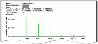
Six Points Best Fit alignment |
Follow the on-screen prompts to select or measure
six points. A typical procedure is to measure three points on
the top surface to level to the Z Axis. Measure two points on
the front surface to rotate to the X Axis. Then measure one point
to define the origin for the Y axis. Click Finish.
This establishes the correct origin for the alignment. PC-DMIS
inserts the Best
Fit 3D Alignment. Following execution, PC-DMIS displays a
3D Alignment Best Fit Graphical Analysis in the Report window.
|
For additional ways of creating alignments see the "Creating and Using Alignments" chapter.