Step 9 - Measure the Datum Sphere with PEM Extension(s) (optional)
This example for the ACR1 Probe Changer uses two Autojoint extensions (PEM modules) in ports 7 and 8.
WARNING: At different times throughout this procedure, the machine moves in DCC mode. When this happens, to avoid injury, stay clear of the machine. To avoid hardware damage, run the machine at a slower speed.
The system displays this message:
Please attach only the extension to be used in port 7. When you click OK if you have a wrist it may rotate (if needed) to allow for any rotation of the bottom joint. When prompted then take 1 hit on the bottom of the auto joint with the probe changer datum sphere. Be careful to avoid the small pins and holes and take the hit on a flat area.
After you complete this point the auto joint diameter will be measured in DCC.
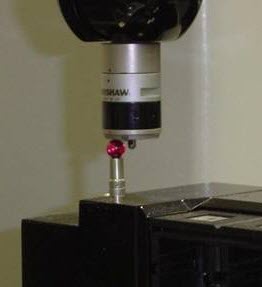
If you use PEM (extensions), it is necessary to also take a manual hit at the bottom of each one as shown in the picture below.
Manual hit at bottom of each PEM
When you have completed these steps, click OK. DCC measurement begins.
Please attach only the extension to be used in port 8. When you click OK if you have a wrist it may rotate (if needed) to allow for any rotation of the bottom joint. When prompted then take 1 hit on the bottom of the auto joint with the probe changer datum sphere. Be careful to avoid the small pins and holes and take the hit on a flat area.
After you complete this point the auto joint diameter will be measured in DCC.
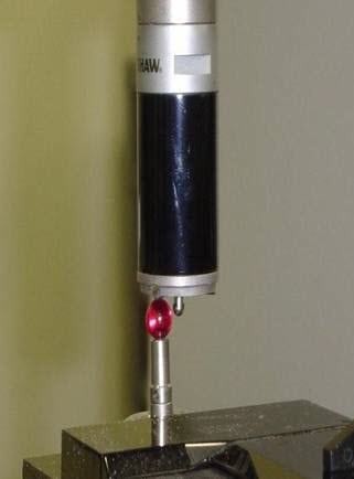
The picture below shows the manual hit being taken with the 50mm PEM identified as being stored in port 8.
When you have completed these steps, click OK. DCC measurement begins.
All measurement is now complete. Please reconnect the probe used to measure the ports and then click OK.
This completes the calibration of the ACR1 Probe Changer. The next step describes how to review your calibration.