CW43L
Probe Changer.
CW43L
Probe Changer.This topic describes how to calibrate the CW43L
Probe Changer.
The CW43 Probe Changer can hold two different kinds
of ports: normal
ports and three-axis ports (ports that hold probes
that can rotate in three axes).
The CW43L Probe Changer calibration procedure requires you to perform the calibration using a probe with the wrist map in order to properly calculate the port locations. Once you calibrate the probe changer, you can then use it to change probes regardless of whether or not they actually use the wrist map.
Before you start the calibration process, ensure that the installation personnel have mechanically aligned all of the ports so that the front face and the top of the ports are parallel to the movement of the machine's ram. If the ports are not properly aligned in this fashion, problems can occur during a probe change operation.
Step 1 - Select the CW43 Probe Changer
In the Probe Changer dialog box (Edit | Preferences | Probe Changer), select the Type tab.
In the Probe changer type list, select CW43L.
To make this probe changer active and load the settings that are relevant to this probe changer, click Apply. Other tabs become visible after you click Apply.
In the Number of probe changers box, type the number of different types of probe changers. Generally, this is 1.
The Active probe changer list now reads: Probe Changer 1 : Type= CW43L.
Step 2 - Define the Ports
In this step, define the number of ports for your probe changer as well as the hardware held in each port.
Select the Ports tab.
In the Number of ports box, specify the number of ports used on your probe changer.
Click Apply.
Expand each port in the list, and define the probe file names that correspond to the hardware (probe or extension) that each port holds. You can do this now or any time after this point.
Click Apply when you are finished.
Getting Around Three-Axis Ports
If you have a three-axis port, notice that it sticks out from the rack more than the normal ports. This may cause clearance problems when performing a probe change operation. To help avoid crashing into these ports, we recommend that you install this type of port on the ends of the probe changer: either on the top or the bottom on a vertical probe changer or on the left or right sides of a horizontal probe changer. If you cannot do this due to space constraints in your environment, modify the default clearance distance that the probe uses when moving to and from the different ports. You can do this by accessing the PC-DMIS Settings Editor and modifying the TCRackClearance or TCRack3AxisClearance entry in the next step.
TCRackClearance - This entry is the clearance distance in front of a normal port. It has a default value of 150 mm.
TCRack3AxisClearance - This entry is the clearance distance in front of a three-axis port. It has a default value of 300 mm.
Step 3 - Define the Three-Axis Port and Change Clearance Distances
You only need to perform this step if you have a three-axis port (a port capable of storing a three-axis probe). If not, go to the next step. You can perform this step later, but it is recommended that you do it now. This step essentially tells PC-DMIS which port is the three-axis port and whether or not you intend to perform load or unload operations automatically for that port.
Click OK to close the Probe Changer dialog box.
Exit the PC-DMIS application.
Launch the PC-DMIS Settings Editor.
Navigate to the Leitz section.
Select the CW43LThirdAxisTCSlot or CW43LThirdAxisTCVerticalSlot entry according to the port type mounted on the tool changer. The CW43LThirdAxisTCSlot entry is used for the old port type, where the third axis lies horizontally. The CW43LThirdAxisTCVerticalSlot entry is used for the new port type, where the third axis lies vertically. By default, these entries have a value of -1, which means that a three-axis port is not available on the probe changer.
If you plan to manually load and unload the three-axis probe from the port yourself, you should set this value to 0.
If you plan to have PC-DMIS automatically load and unload the probe, you should set this value to the port number that holds the three-axis probe.
Ensure that the CW43LTTest3AxisSlotTC
entry is set to True. There are two
LED lights in a magnetic relay located on the
back of a three-axis port: a green light and an amber light. The green
light means that the port relay has power. The amber light is only
illuminated if the three-axis joint is physically located in the port.
A True value for this entry checks for the
amber light and is an indication to the CMM controller that it is
safe to apply the 24 volt DC motor power to the three-axis joint.
During a probe changer operation, NEVER attempt to manually change the three-axis probe while the green LED light on the top of the three axis joint is illuminated. An illuminated green LED light signifies that motor power (+24V DC) is present. If a probe change is done while there is motor power, it could cause a voltage spike that would damage the third axis motor. The same is possible for other voltage signals (+5V DC, +12V DC, and so on) needed for items that may attach to the third axis (Perceptron probe, NC100 video probe, and so forth). This applies only when the joint is connected to the probe head.
Starting with PC-DMIS 2019 R2, PC-DMIS no longer supports the Perceptron laser sensor. While you may still be able to install PC-DMIS 2019 R2 and later, PC-DMIS displays an error if you attempt to run measurement routines that use the Perceptron scanner. For additional information, please contact Technical Support.
If needed, you can also modify the clearance distances for the TCRackClearance and TCRack3AxisClearance entries. You should only need to do this if your three-axis port could not be placed on the ends of the rack.
If you need to change the third-axis angle position when the probe is inside the port, set the desired value for the CW43LTThirdAxisSlotAngle entry. The default value is -1. If the value is -1, the angle value is the default value (according to the port type). You can set a value in these ranges:
0 to 180
0 to -180
If needed, modify the port cover lift direction in the CW43LThirdAxisTCLeftToRightLift entry. To determine the value, stand in front of the probe changer port and check the direction.
If the port cover lift direction is from left to right, set the value to True (this is the default value).
If the port cover lift direction is from right to left, set the value to False.
PC-DMIS uses the value that you set for the CW43LThirdAxisTCLeftToRightLift entry only when the value for the CW43LThirdAxisTCVerticalSlot entry is not set to -1.
Save any changes and then close PC-DMIS Settings Editor.
Restart PC-DMIS and reload your measurement routine.
Select Edit | Preferences | Probe Changer to open the Probe Changer dialog box.
Step 4 - Prepare for Calibration
This step defines the probe file and tip angle to use during the calibration process.
Select the Calibrate tab.
In the Active probe file list, select the probe to use.
In the Active tip list, select the tip angle to use. The tip angle you use depends on your specific machine. This tip angle is used throughout the entire calibration process.
Step 5 - Begin Calibration
In this step, you need to decide whether to calibrate a single port in the probe changer or calibrate all of the ports, and then start the calibration procedure.
Decide the type of calibration to perform: either Single port calibration or Full calibration.
If you selected Single port calibration, the Probe changer port list becomes available for selection. In the Probe changer list, select the single probe to calibrate.
If you selected Full calibration, PC-DMIS calibrates all the available ports on your probe changer, starting with the first port and moving sequentially through all the ports.
Click the Calibrate button. PC-DMIS prompts if it is OK to rotate to the previously defined probe angle.
Click OK. The probe rotates to the defined angle, and a message box appears prompting you to take three hits.
Step 6 - Calibrate by Taking Three Hits
In this step, the probe is manually moved to take three hits, one on three different faces of each port being calibrated. For a full calibration, hits on the first defined port is taken and then move sequentially to the second port, and so on until the last. For a single port calibration, only hits on the one port being calibrated is made.
For a vertical probe changer:
Take the first hit anywhere on the top of the top of the port. Press Done.
Take the second hit anywhere on the side of the port nearest the ram of the machine. Press Done.
Take the third hit anywhere on the front face of the port. (If this is the three-axis port, take the hit on the face to which the hinges of the port cover are attached.) Press Done.
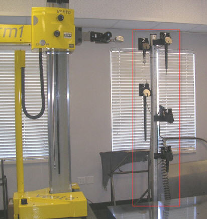
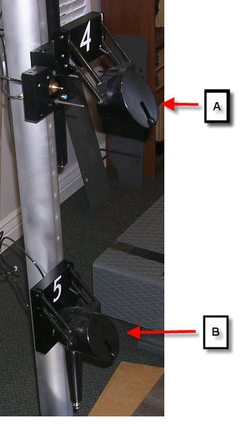
Examples of taking three hits on a vertical probe changer. The following two pictures provide examples of the surfaces where the three hits should be taken for both a three-axis probe port and a normal probe port.
Three-axis probe port on a vertical rack

Normal probe port on a vertical rack
A
- First hit on the top surface
B - Second hit on the side closest to the ram
(depending on where your CMM ram is located, this could be on the other
side)
C - Third hit on the front face
For a horizontal probe changer:
Take the first hit anywhere on the top of the top of the port. Press Done.
Take the second hit anywhere on either side of the port. Press Done.
Take the third hit anywhere on the front face of the port. (If this is the 3 axis port, take the hit on the face to which the hinges of the port cover are attached.) Press Done.
Step 7 - Define a Mount Point
In this step, you define a safe location and probe head angle in front of the rack where the CMM is able to reach all the ports. This is called the "mount point".
The mount point location is NOT the same thing as the distance in front of the probe changer as defined by the TCRackClearance and TCRack3AxisClearance entries.
Select the Mount Point tab.
In the Probe head wrist angle boxes, use the A angle and B angle boxes to define the probe head angle to use when the probe head is at the mount point location.
Use the jog box to manually move the probe to where you want your mount point, and then click the Read Machine button. PC-DMIS pulls in the XYZ location from the CMM.
Click Apply and then OK.
You are now done with the calibration of the CW43 Probe Changer. You can now perform probe changes.
Remember, during a probe changer operation, NEVER attempt to manually change a three axis probe while the green LED light on the top of the three axis joint is lit. This applies only when the joint is connected to the probe head.