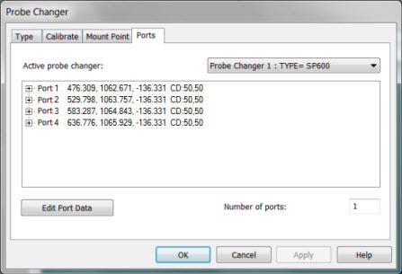
For the SP600 Probe Changer, once the DCC measuring finishes, select the Ports tab in the Probe Changer dialog box (Edit | Preferences | Probe Changer). This tab displays the calibration information for the location of each calibrated port. For example:
Probe Changer dialog box - Ports tab with calibration results
When you view the results, look for the following. Some things to watch for are the position of the rack and the spacing of the ports. Any significant deviations from these expectations may be due to a bad hit.
This rack is not necessarily aligned parallel to any axis of the CMM.
However, the X and Y values should show equal spacing between ports, roughly 53.5 mm apart.
Similarly, the Z values should be nearly identical, since the ports are all at the same height.
The results during measurement routine execution are:
Probe entities that are added to each of the ports are automatically picked up from that location whenever PC-DMIS executes a LOADPROBE command for that probe.
The probe body moves to the mount point and then into the "unload" port (the port that used to contain the currently used probe entity), which pushes the lid backwards. The current "puck", a black conical piece of hardware that connects to the bottom of the probe body, is held in place by the rack while the probe body lifts away to detach.
From there, the probe moves over to the next "load" position. The magnetic connection automatically engages to load the new module.
It then moves back to the rack’s mount point.
From there, it continues to measure.