(This item pertains to the Probe Utilities dialog box, accessible through Insert | Hardware Definition | Probe.)
You can double-click on a component in the Probe description area (in the Probe Utilities dialog box) to open the Edit Probe Component dialog box. You can use this dialog box to hide some probe graphics to provide a better view of the features. This is useful in cases where the part geometry is particularly dense.
The options that appear in this dialog box depend on the component you selected.
Default Options
The following two options apply to all components:

Edit Probe Component dialog box
Draw this component - If you select this check box, PC-DMIS draws the component in the Graphic Display window.
Default rotation angle about connection - This value defines a rotation angle about the connection. The rotation angle is primarily used to manually define the angle of knuckle attachments. You can type any angle from +180° to -180°. 0 is the default angle.
To hide probe graphics:
In the Probe description area, locate the part of the probe that you want to hide from view.
Double-click on that probe component to show the Edit Probe Component dialog box.
Clear the Draw this component check box.
Click the OK button to close the Edit Probe Component dialog box. Notice that PC-DMIS redraws the probe graphics without the indicated component and all other components above it in the Probe Utilities dialog box.
Additional Option for Star Probe Components
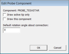
If you have a star probe, you can make it so that only the current tip is visible in the Graphic Display window. You can do this with the Draw Active Tip only check box in the Edit Probe Component dialog box.
To see the check box, from the Probe Description area, double-click on the probe head component.

Edit Probe Component dialog box - Star Probe
Draw active tip only - If you select this check box, PC-DMIS hides any non-active probe tips instead of merely highlighting the active probe tip in the Graphic Display window. If you clear this check box, PC-DMIS highlights the active probe tip as usual.
Additional Options for Disk Stylus Components
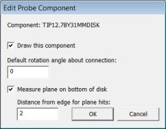
For calibration of a disk stylus when used with an analog probe, two additional options are included.

Edit Probe Component dialog box - Disk Stylus
Measure plane on bottom of disk
If you select this check box, four hits are taken on the bottom of the disk to calculate a plane and therefore determine a measured vector associated with the plane of the disk.
If you clear this check box, PC-DMIS does not take any plane hits, and there is no measured vector. The vector for the plane of the disk is the theoretical value from the model of the probe.
For a new probe, the default value is determined by the ProbeQualAnalogDiskUsePlaneOnBottom entry in the ProbeCal section of the PC-DMIS Settings Editor. If this entry is set to 1, PC-DMIS measures the plane. If this entry is set to 0, PC-DMIS does not measure the plane.
Distance from edge for plane hits
When you measure the plane, PC-DMIS distributes the hits in a circular pattern from this distance back from the outer edge of the disk. The radius for the pattern of the plane hits is the disk radius minus this distance.
For a new probe, the default value is determined by the ProbeQualAnalogDiskBottomHitsDistanceFromEdge entry in the ProbeCal section of the PC-DMIS Settings Editor. The units for this entry are always in millimeters. However, the value that you enter in the Distance from edge for plane hits box is in the units of the measurement routine that you are using (that is, either inches or millimeters).
In 2012 MR1 and higher, the ProbeQualAnalogDiskBottomHitsDistanceFromEdge and ProbeQualAnalogDiskUsePlaneOnBottom entries provide the initial defaults for new probes. You can then define specific settings for individual probes in the Edit Probe Component dialog box.