
This icon only functions if you are working with one of these supported features: Surface Point, Edge Point, Line, Plane, Circle, Cylinder, and Round Slot.
If selected, PC-DMIS detects hit targets that would normally occur in voids (empty spaces) on the CAD model and repositions them to a safe location, usually near the edge of the void.
As an example, the first image shows the behavior of a line created right on the edge of two different surfaces with no Depth or Void Detection enabled.
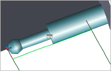
Example of a line generated with Void Detection disabled
In this case, PC-DMIS places the hits for the line just on the edge. If you enable Depth Detection without Void Detection enabled, the hits are as far from the edge as the depth parameter.
The next image shows the behavior when Void Detection is enabled on the same line and Depth Detection is set to 0 (zero).
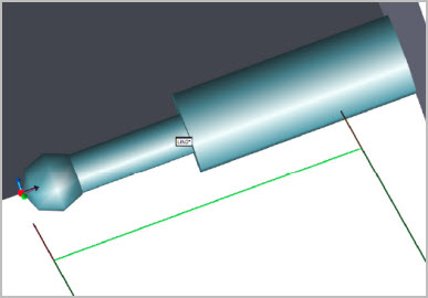
Example of a line generated with Void Detection enabled
The Void Detection algorithm is designed to add some intelligence to the hits distribution. Due to the instability of calculating a line on or very near to an edge, a "security distance" is determined. PC-DMIS then uses this to place the hits for the feature. The "security distance" is based on a multiple of the probe's radius.
In QuickFeature mode, you can select multiple colinear or coplanar entities. Void Detection creates a hit pattern that considers all selected entities. For details on how to turn this function On and Off, see the "VoidDetectionNewAlgorithm" topic in the Settings Editor documentation.
You can also drag-select hits to determine an edge. Note that when you drag-select hits with Void Detection set to On, the Void Detection algorithm is still used to calculate the starting point of the drag operation. Once dragging starts, however, the Void Detection option is automatically set to Off, and the remaining hits are detected manually. The Void Detection algorithm is used to intelligently define the path while drag-selecting manually determines the path.