You can construct a circle from a cone at a specified diameter of the cone, or you can construct a circle at a given height along that cone from the current alignment plane. A Cone Circle feature that you construct at a given height is sometimes known as a "gage diameter" or "gage point".
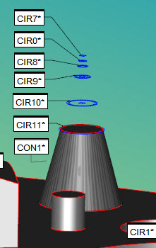
Multiple circles created at different heights from the cone input feature of CON1
Understanding the Height Value
If you construct a circle at a given height, PC-DMIS calculates the circle in this way:
It creates a plane from the reference point and the reference vector.
It then creates a parallel offset plane from this plane by the height value. This parallel plane intersects with the cone axis, and the intersection creates the location of the resulting circle feature. The diameter of the circle is the diameter of the cone at that intersection point.
Available reference point (REF_POINT) options:
CONE_VERTEX
CONE_START
CONE_END
ORIGIN
Available reference vector (REF_VECTOR) options:
CONE_VECTOR
WORKPLANE
ZPLUS
ZMINUS
XPLUS
XMINUS
YPLUS
YMINUS
For example, if you use the origin as a reference point and ZPLUS as your reference vector, PC-DMIS creates a plane from the origin point and the ZPLUS vector. Then it creates a parallel plane at the given height value, and where it intersects with the cone, it creates the circle feature. Your Edit window's code might look something like this:
CIR2=FEAT/CIRCLE,RECT,OUT
THEO/-67.295,2.595,-7.152,0.0310723,-0.0214397,-0.9992872,29.411
ACTL/-67.295,2.595,-7.152,0.0310723,-0.0214397,-0.9992872,29.411
CONSTR/CIRCLE,CONE,CON2,HEIGHT,5,REF_POINT = ORIGIN,REF_VECTOR = ZPLUS
To construct a Cone Circle:
Access the Construct Circle dialog box (Insert | Feature | Constructed | Circle).
From the Method list, select the Cone option.
Select one feature. The type must be a cone.
Select either DIAMETER or HEIGHT from the Type list.
Type a value for the diameter or height into the Value box.
If you selected Height:
Select a reference point from the Point list.
Select a reference vector from the Vector list.
Click the Create button.
The Edit window command line for this option would read:
CONSTR/CIRCLE,CONE,DIAMETER,feat_1
or
CONSTR/CIRCLE,CONE,HEIGHT,value,REF_POINT=point,REF_VECTOR=vector,feat_1