Similar to the cone and sphere circle constructions, this type of construction creates a circle from a cylinder at a height (or distance) along the defined vector. The resulting circle feature will have the same diameter as the reference cylinder. This type of construction takes three inputs: a height Value, a reference Point, and a Vector.
Value - This box lets you type the height value. PC-DMIS constructs the circle at this distance from the selected reference point and along the selected vector. A positive value uses the same direction as the vector. A negative value will use the opposite direction along that vector.
Point - This list lets you define a reference point from which PC-DMIS constructs the circle. It has these options:
CYLINDER_START - The start location of the cylinder. This point is located at the centroid of the circle defined from the first level of hits.
CYLINDER_END - The end location of the cylinder. This point is located at the centroid of the circle defined from the last level of hits.
ORIGIN - The origin of your coordinate system.
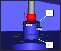
These images show some sample start and end locations for different cylinder types:
A - A sample CYLINDER_START
location for an Auto Cylinder
B - A sample CYLINDER_END location for an Auto
Cylinder
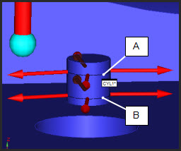
A - A sample CYLINDER_START
location for a Measured Cylinder
B - A sample CYLINDER_END location for a Measured
Cylinder
Vector - This defines the vector of the constructed circle and the vector along which the height value is applied. Eight reference vectors are available: CYLINDER_VECTOR, WORKPLANE, ZPLUS, ZMINUS, XPLUS, XMINUS, YPLUS, and YMINUS.
To construct a cylinder circle:
Access the Construct Circle dialog box (Insert | Feature | Constructed | Circle).
From the Method list, select the Cylinder option.
Select a single cylinder feature.
Select the reference point from the Point list.
Select a reference vector from the Vector list. The direction on which the cross section is taken is chosen from the Vector list.
Type a distance into the Value box.
Click the Create button.
The Edit window command line for this option would
read:
CONSTR/CIRCLE,CYLINDER,feat1,HEIGHT,value,REF_POINT
= point,REF_VECTOR = vector