You can construct a mid line between a line (cone, slot, cylinder, or plane) and a line (cone, slot, cylinder, or plane). PC-DMIS creates a line (mid line) such that each of its points is the same distance from both input lines. You can construct mid lines from lines that are parallel as well as lines with any angle between them. The lines do not have to intersect.
The mid line centroid is a point on the line segment between the centroids of the input lines that is the same distance from both lines (it is not necessarily the midpoint of the line segment).
The direction of the mid line vector depends on the location of the mid line centroid and on the two input vectors, with the sense of the mid line vector determined by the first line vector. Expressed mathematically, if the first line vector is V1 and the second line vector is V2 then the direction of the mid line vector is generally either V1 + V2 or V1 - V2.
To construct a mid line:
Open the Construct Line dialog box (Insert | Feature | Constructed | Line).
From the Method list, select the Mid option.
From the Feature list, select the first feature. It must be either a line, cone, cylinder, or slot.
From the Feature list, select the second feature. It must be either a line, cone, cylinder, or slot.
If you want to change the feature theoretical values, select the Feature theoreticals check box and type in the values. For details, see the "Specifying Feature Theoreticals" topic in the PC-DMIS Core documentation.
Click the Create button.
The Edit window command line for this option would read:
CONSTR/LINE,MID,feat_1,feat_2,length
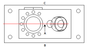
A - Constructed line (a mid
line) equally spaced between two lines (FRONT and BACK)
B - FRONT
C - BACK
Constructing a Mid Line from Two Lines