You can construct a circle from a segment of a Linear Open, Linear Close, or Basic Circle scan. PC-DMIS creates an arc from part of the scan. The details of the construction are included further in this discussion.
To construct a scan segment circle:
Access the Construct Circle dialog box (Insert | Feature | Constructed | Circle).
From the Method list, select the Scan Segment option.
Select a previously created Linear Open, Linear Close, or Basic Circle scan.
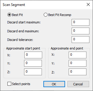
Click the Segment Data button to open the Scan Segment dialog box.
Scan Segment dialog box
Select either the Best Fit or BF Recomp option.
Select the portion of the scan used in the construction from this dialog box.
Type the number of points to potentially discard in the Discard Start and Discard End Maximum boxes.
Type a distance from the best fit circle into the Discard Tolerance box. This tolerance is a form tolerance; it allows you to control what end points PC-DMIS accepts as part of the arc. If the distance from the scan point to the best fit arc is greater than this tolerance value, then PC-DMIS discards the end point.
Select the Select Points check box to input the Approximate Start and End Points of the scan, and then click in the Graphic Display window to fill in the X, Y, and Z fields. You can click anywhere in the Graphic Display window, however, PC-DMIS will place the point on the scan nearest to where you clicked. You can also type in the point values.
Click OK to accept the data and close the Scan Segment dialog box.
Click Create to construct the arc from the scan.
The Edit window command line for this option reads:
CONSTR/CIRCLE,SCAN_SEGMENT,fit_type,feat_1,start_x,start_y,start_z,end_x,end_y,end_z,discard_start,discard_end,tolerance
If you want more than one arc or line from a given scan, then you will need to add another command for a different section of the scan.
More: