For details on extracting Auto features from a Mesh, see the "Extracting Auto Features from a Mesh" topic in the PC-DMIS Laser documentation.
For details on extracting Auto features from a Pointcloud (COP), see the "Extracting Auto Features from Pointclouds" topic in the PC-DMIS Laser documentation.
You can construct an extreme point from a measured feature, scanned object, or from a scanned cloud of points (COP) or MESH.
To do this:
Ensure that your measurement routine has a measured feature, scanned object, or a Pointcloud (COP) or Mesh command.
Access the Constructed Point dialog box (Insert | Feature | Constructed | Point).
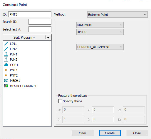
Construct Point dialog box - Extreme Point
Select the Extreme Point option from the Method list. This changes the Constructed Point dialog box to show the options to create an extreme point.
From the Feature List area, select the desired feature.
The Options area consists of three combo-boxes and the Feature theoreticals area. From the first combo-box, select either MAXIMUM or MINIMUM.
From the second combo-box, select the direction (XPLUS, XMINUS, YPLUS, YMINUS, ZPLUS, or ZMINUS) for the extreme point calculation. This is the direction that PC-DMIS uses to find the extreme point.
If you selected MAXIMUM in step 5, PC-DMIS defines the extreme point as:
If you selected XPLUS, XMINUS, YPLUS, YMINUS, ZPLUS, or ZMINUS, the largest value from the origin along the selected axis relative to the start point.
If you selected 2D_PR or 3D_PR, the longest polar radius from the origin relative to the start point.
If you selected MINIMUM in step 5, PC-DMIS defines the extreme point as:
If you selected XPLUS, XMINUS, YPLUS, YMINUS, ZPLUS, or ZMINUS, the smallest value from the origin along the selected axis relative to the start point.
If you selected 2D_PR or 3D_PR, the shortest polar radius from the origin relative to the start point.
If you select the 2D_PR (2D-Polar Radius) option, PC-DMIS enables another combo-box just below the second combo-box. Use this to select the workplane (ZPLUS, XPLUS, YPLUS, ZMINUS, XMINUS, or YMINUS) in which to apply the 2D-Polar Radius.
Select the 3D_PR (3D-Polar Radius) option to define a 3D polar radius direction.
Use the third combo-box to define the start point that PC-DMIS uses to calculate the extreme point.
CURRENT_ALIGNMENT - Select this option to specify the origin (0, 0, 0) and orientation of the currently active alignment.
USER_DEFINED - Select this option to specify a new centroid starting point and starting axis vector. If you choose one of the polar radius calculations from the second combo-box (2D_PR or 3D_PR), you can only specify the new centroid starting point.
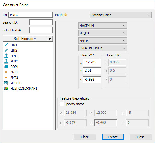
When you select the USER_DEFINED option from the third combo-box, PC-DMIS creates a local alignment using the supplied X, Y, and Z values as the origin, the current workplane as the axis, and then rotates the primary axis using the supplied I, J, and K values. You can type the values into the X, Y, and Z boxes or click inside one of the boxes and then click a feature to use its centroid. Similarly, you can type the values into the I, J, and K boxes or click inside one of the boxes and then Alt + click a feature to use its direction.
From the Feature theoreticals area, you can select the Specify theos check box. Here you can set the theoretical X, Y, Z and I, J, K values for the constructed extreme point.
Click the Create button. Based on the parameters that you specified in the dialog box, PC-DMIS returns the calculated extreme point.
PC-DMIS created the command in the Edit window:
PNT1=FEAT/POINT,CARTESIAN,tog1
THEO/<theoXyz>,<theoIjk>
ACTL/<actXyz>,<actIjk>
CONSTR/POINT,EXTREME,feat1,tog2,tog3,optTog,tog4,udXyz,udIjk
Where:
tog1 – This is either YES or NO based on the values entered for the Specify theos option.
feat1 – This is the input feature selected in step 4 that PC-DMIS uses to find the extreme point.
tog2 – This is either MAXIMUM or MINIMUM selected in step 5.
tog3 – This is either XPLUS, XMINUS, YPLUS, YMINUS, ZPLUS, ZMINUS, 2D_PR (2D-Polar Radius), or 3D_PR (3D-Polar Radius). This specifies the direction to search for the extreme point.
optTog – This is only available when tog3 = 2D_PR. This can be ZPLUS, XPLUS, YPLUS, ZMINUS, XMINUS, or YMINUS.
tog4 – This is either CURRENT_ALIGNMENT or USER_DEFINED. When you select CURRENT_ALIGNMENT, PC-DMIS calculates all extreme points from the origin (0, 0, 0). If you select USER_DEFINED, you can specify a new starting point and direction to calculate from. This is a way of creating a temporary alignment for the extreme point calculation.
udXyz – This is the user-defined X, Y, Z point that PC-DMIS uses to calculate the extreme point from.
udIjk – This is the user-defined I, J, K direction vector. This allows you to specify a new starting direction axis.