Equate Alignment dialog box for Part moved on machine
For Equate Alignment to function properly:
This command works with both regular alignment blocks (START_ALIGN/END_ALIGN pairs) and external recalled alignments. The external alignment must be recalled using the RECALL/ALIGNMENT, EXTERNAL command before it becomes available for use in the dialog box.
Equate new alignment:
This list allows you to select the new alignment you are equating with your original created alignment.
With original alignment
This list allows you to select the previously created original alignment to which you are equating the new alignment.
For example, to measure a dimension that references features on two sides of the part that are not accessible from a single part orientation:
Measure the alignment features on the first side of the part.
Create the original (fully-constrained) alignment.
Measure all required features that can be reached from the first orientation of the part.
Move the part to its new position.
Switch to Manual mode.
Recall the startup alignment (Machine Coordinate System).
From CAD or the print values, program the new alignment features in Manual mode and in DCC mode.
The origin must be the same, and the axis must be in the same direction as the axis of the alignment to which you are equating. It is easiest to understand this if you imagine that the original origin and axes' arrows are glued onto the part before moving it. The new alignment places the origin and axes' arrows in the same position with respect to the part.
Select the Insert | Alignment | Equate menu option. The Equate Alignment dialog box appears.
In the Equate Type area, select Part moved on machine. Note that when editing an existing Equate alignment command, the Equate Type area is disabled.
In the Equate new alignment list, select the new alignment.
In the With original alignment list, select the original alignment.
Click the OK button to insert the new EQUATE alignment command into the measurement routine. The CAD model won't move relative to the alignment axes, but the measured values will move once PC-DMIS executes the equate alignment.
The Edit window command line for this option reads:
EQUATE/"name1"TO ALIGNMENT,"name2"
Note about Clearance Planes
After equating the new alignment, any existing clearance planes continue to use the same "relative" plane from the previous alignment. This means after you have moved your part, you should define new clearance planes to avoid incorrect clearance plane moves.
Example:
In this setup, we want to measure all features in the X-, X+, Y-, Y+, and Z+ planes. The features in the Z- direction are not accessible which requires a second setup.
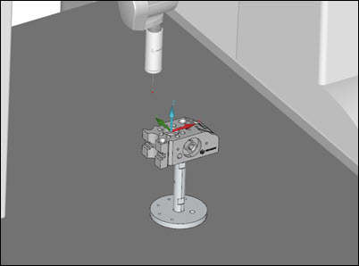
Example setup #1
Before you switch to the second setup, remember to switch to Manual mode and recall the startup alignment (step 5 above).
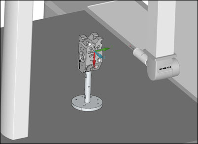
Example setup #2