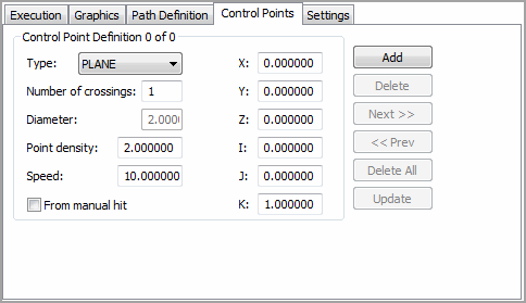

Control Points tab from a scan dialog box
The Control Points tab only appears if you use an analog probe head that allows continuous contact scanning.
The Control Points tab in the scan dialog box (Insert | Scan) enables you to add control points to your scan. Control points interrupt the normal scan functions and allow you to define specific locations on the scan which alter the scan speed, point density, or both. Good continuous scans often require different scan speeds and/or point densities for different parts of the scan.
The ability to add control points has been added to these types of scans:
Linear Open
Linear Closed
Patch
Section
Line (Basic Scan)
The Control Points tab contains the Control Points Definition area. This area lets you define each control point. It contains the following items.
Type list
This list defines the type of control point. The available types include:
Plane
PLANE, X, Y, Z, I, J, K, Num Crossings, Scan Speed, Point Density
Sphere
SPHERE, X, Y, Z, I, J, K, Num Crossings, Scan Speed, Point Density,
Diameter
Cone
CONE, X, Y, Z, I, J, K, Num Crossings, Scan Speed, Point Density, Angle
Cylinder
CYLINDER, X, Y, Z, I, J, K, Num Crossings, Scan Speed, Point Density,
Diameter
These types are similar to the boundary points.
The Control Points tab has these options:
Number
of crossings box
This box defines the number of times the probe must cross the interrupt
boundary before adjusting the specified parameters.
Diameter
box
This box defines the diameter of the Cylinder
or Sphere control point.
Angle
box
This box defines the half angle of the Cone control
point.
Point
density box
This box defines the density of the points that are read into the scan
data during a continuous contact scan. This is listed as the number of
points per mm.
Speed
box
This box defines the speed of the machine while it traverses the part surface
performing scans.
From
manual hit check box
If you select this check box, you can define the control point's XYZ and
IJK location by manually taking a hit with the probe or by clicking on
the part model.
XYZ
boxes
These boxes define the XYZ location of the control point.
IJK
boxes
These boxes define the IJK vector of the control point.
Add
button
Adds a new, undefined control point.
Delete
button
Deletes the current control point.
Next
button
Goes to the next control point. The boxes in the area change to show the
new point's data.
Prev
button
Goes to the previous control point. The boxes in the area change to show
the new point's data.
Delete
All button
Deletes all the control points in the scan.
Update
button
Updates all the control points in the scan with the setting for the current
control point.
More: