
You can edit boundary points by double-clicking the number of the desired point in the ‘#’ column in the scan dialog box (Insert | Scan).
This displays the Edit Scan Item dialog box, which enables you to edit the X, Y, and Z values.
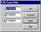
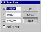
Edit Scan Item dialog boxes with the Flip button and Point at Hole check box
You can vary the column widths of the Boundary Point list by changing the width of the list display column header. To do this, select the right or left edge of a column header with the left mouse button and pull the edge to the desired size. You individually set and determine the width of each list display. This information is saved in the INI file to be used each time you change the fields.
Flip:
The Flip button is only available when you edit a vector. Click this button to flip the selected vector.
Point At Hole:
The Point At Hole check box only becomes available when you work with Section scans. It allows you to change a non-hole point to a hole point.
A hole point defines where a linear section scan jumps over a hole that's found in its path. After you click the Cut CAD button, PC-DMIS places hole points on either side of any hole that interrupts the section scan.
Hole points are defined with the letter "H" after the point number (for example, 1H, 2H, 3H, etc.). These points, like any boundary point, are added to both the Boundary Points list and on the part model in the Graphic Display window.
The Point At Hole check box is only available for non-hole points that you need to change to hole points. If you have a hole point that needs to be changed to a non-hole point, delete the hole point and create a new non-hole point.