When setting up the start, direction, and end points of the scan, PC-DMIS allows you to see a graphical representation of the initial touch vector, the direction vector, and the vector that is normal to the boundary plane where the scan will stop.
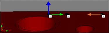
These vectors are shown as blue, green, and orange colored arrows in the Graphic Display area of your part.
Colored arrows showing vectors
Vectors and their graphical representations are:
Initial Touch: Blue arrow
Direction: Green arrow
Boundary Plane: Orange arrow
More:
Creating Auto Features: Introduction
Quick Ways to Create Auto Features
Graphical Representation of Auto feature and QuickFeature Vectors