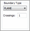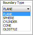

The Boundary Type area on the Execution tab in the scan dialog box (Insert | Scan) creates an imaginary feature that acts as a boundary around a scan's end point. By default, this feature is a plane at the end point that when crossed one time stops the scan. However, you can define the end boundary type to be a different type of feature.
Boundary types are available only for Linear Open, Linear Close, Patch, Section, and Rotary scans in DCC mode.
The area contains these items:
Boundary Type list

The boundary type list lets you choose how a scan ends. Each boundary type uses a value from the Crossings box.
Plane
- The scan stops after the probe crosses the plane at the end point the
given number of times. 

Sphere
- The scan stops after the probe crosses (breaks) the sphere at the end
point the given number of times. 

Cylinder
- The scan stops after the probe crosses (breaks) the cylinder at the
end point the given number of times. The cylinder is unbounded (i.e. is
considered infinite in length). 

Cone
- The scan stops after the probe crosses (breaks) the cone at the end
point the given number of times. The cone is unbounded (i.e. is considered
infinite in length). 

OldStyle
- (Retained for backwards compatibility) 

Crossings box

The Crossings box determines how many times a scan crosses the selected boundary type before stopping the scan. For example, if you specify that the number of crossings is two, the scan will stop once the probe's ball center crosses the given condition’s surface (planar, spherical, cylindrical, conical etc.) two times.
Linear Closed scans always require at least two boundary crossings even if the Crossings box specifies a lower number.
Radius
box
The Radius box appears when you select either
Sphere or Cylinder
as your boundary type. It lets you define the radius of that boundary
type feature.
Angle
box
The Angle box appears when you select Cone
as your boundary type. It lets you define the cone's total 'included'
angle.
You can change the boundary condition at any time for a scan. If you choose a new condition for a DCC scan, PC-DMIS applies it to all basic scans making up the DCC scan. If, however, you chose to change a specific value in a condition, for example, maybe the radius of the sphere boundary type, PC-DMIS does not propagate that change to the basic scans. You would have to change that value in each basic scan yourself.