This procedure helps you insert safe clearance moves for your probe between all features or some features in your measurement routine. This procedure uses information discussed in the "Auto Insert Moves" subtopic in the "Clearance Moves Menu Items" topic above. Refer to that subtopic if you need more information on anything in this procedure.
Choose Operation | Graphic Display Window | Clearance Moves | Auto Insert Moves. The software opens the Auto Insert Moves dialog box.
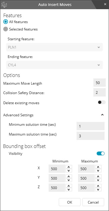
Auto Insert Moves dialog box
From the Auto Insert Moves dialog box, define whether to insert moves between All features or between a range of Selected features.
If you choose Selected features, define a range between two features. Use the Starting feature and Ending feature lists to choose the two features.
If you want a different maximum distance value for your moves, you can modify the default Maximum Move Length value. The higher the value, the lower the amount of time PC-DMIS spends calculating these moves. To prevent the creation of too many moves, this value should be greater than the Collision Safety Distance value.
If you want a different safety distance, you can modify the default Collision Safety Distance value.
If you want to delete all existing moves in your measurement routine before this routine inserts new move commands, move the Delete existing moves switch to on.
If you need to make changes to the Advanced Settings, expand Advanced Settings, and make your changes.
Click OK to start the move insertion process. The software's algorithm calculates and generates safe moves between the features. Once it finishes, it shows a Safe Moves Insertion Report dialog box.
You can press ESC at any time during the generation process to cancel the process and remove any moves the software inserted.
From the Safe Moves Insertion Report dialog box, hover you pointer over the items to review the results. Then click OK to close the dialog box.

Safe Moves Insertion Report dialog box
If the Safe
Moves Insertion Report failed to find a solution between features,
you may need to increase the Bounding box offset size
under Advanced Settings. You may also need to
increase the solution times. You can do that by increasing the Minimum
solution time (sec) and Maximum solution time
(sec) values.
If the results say you have an invalid start or target command position,
this may be due to an incorrect probe tip assigned to measure those commands.

 Diagram
of MOVE/POINT Calculations
Diagram
of MOVE/POINT Calculations