In this step, you'll create a measurement routine, define your probes, define your calibration spheres, and then perform an initial calibration to establish a basic relationship between the two arms. This calibration consists of machines containing wrists with probe extensions at a length of 332 mm. This will result in a calibration of medium accuracy. The probe changer will not be used at this point.
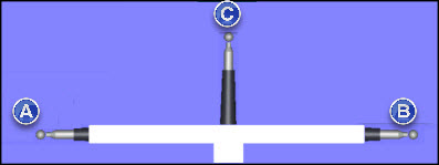
Three calibration spheres mounted on a cross-like fixture with 15 mm calibration spheres will be used for this calibration, like this:
(A) - Sphere 1
(B) - Sphere 2
(C) - Sphere 3
Create a New Measurement Routine
Create a new measurement routine and then load or create the two probes files, PROBE1 and PROBE2, into your measurement routine.
PROBE 1 should have this:
|
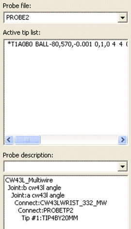
PROBE 2 should have this:
|
They should look like this:
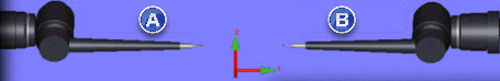
(A) - Probe 1
(B) - Probe 2
Load in a third probe file, name it PROBALL, and give it a 15 mm fixed rigid ball, like this:
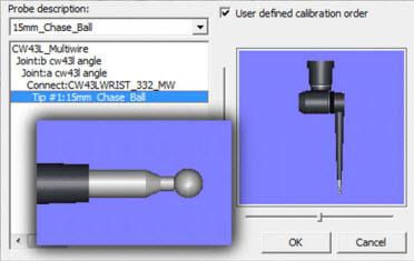
Your measurement routine should look like this:
If your physical structure of the probe and arm are not displayed in the Probe Utilities dialog box (Insert | Hardware Definition | Probe), be sure to edit the USRPROBE.DAT so that the dialog box displays the necessary hardware. For information on data files, see "Understanding Data Files" topic in the "Setting Your Preferences" chapter.
Example usrprobe.dat file edited to contain a flange between the arm and wrist
Define the Calibration Spheres
Access the Add Tool dialog box:
Select Insert | Hardware Definition | Probe.
Click the Measure button.
Click the Add Tool button.
In Tool ID, type SPHERE3.
In Tool type, choose SPHERE.
In the Shank vector IJK boxes, type 0,0,1.
In the Diameter/Length box, type 15.875.
Click OK to close the Add Tool dialog box.
Repeat steps 2 through 6 to define the SPHERE1 calibration sphere. Use 0,-1,0 for the vector.
Repeat steps 2 through 6 to define the SPHERE2 calibration sphere. Use 0,1,0 for the vector.
The information is stored and written to your Tools.dat file.
Click Cancel to close the Measure Probe dialog box.
Click Cancel to close the Probe Utilities dialog box.
Do a Preliminary Calibration
You need to perform a preliminary calibration on SPHERE3 in order to temporarily map the two arms. You can do this calibration without needing to calibrate the actual probe tips for PROBE1 and PROBE2.
Access the Multiple Arm Calibration dialog box by selecting Operation | Calibrate/Edit | Multiple Arm Mode.
Set the First arm list to CMM1.
Set the Second arm list to CMM2.
Choose the Both arms measure tool option.
Type a value of 1 in the Number of spheres to measure box.
Choose the Manual calibration option.
Choose the Origin only option.
Set First arm probe to PROBE1.
Set First arm tip to T1A0B0.
Set Second arm probe to PROBE2.
Set Second arm tip to T1A0B0.
Choose SPHERE3 from the list of available tools.
Click Calibrate. Follow any on-screen prompts.
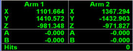
When the calibration finishes, your Probe Readouts window for arm 1 and arm 2 should contain nearly identical X and Z values.
Before Calibration |
After Calibration |
 |
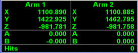 |
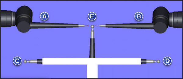
Following a Preliminary Calibration on SPHERE3
(A) - PROBE 1
(B) - PROBE 2
(C) - Sphere 1
(D) - Sphere 2
(E) - Sphere 3
You've successfully calibrated SPHERE3 in order to temporarily map arms 1 and 2. The calibration information is stored within an ArmArm.dat file.
The next step provides information on initiating a more accurate calibration.