DCC Calibration of SPHERE3 Using Arm 1
Continue the calibration in DCC mode for arm 1 measuring SPHERE3. This is the center sphere on the calibration fixture.
Swap out the 15 mm tip on the Arm 1 extension with the TP2 tip.
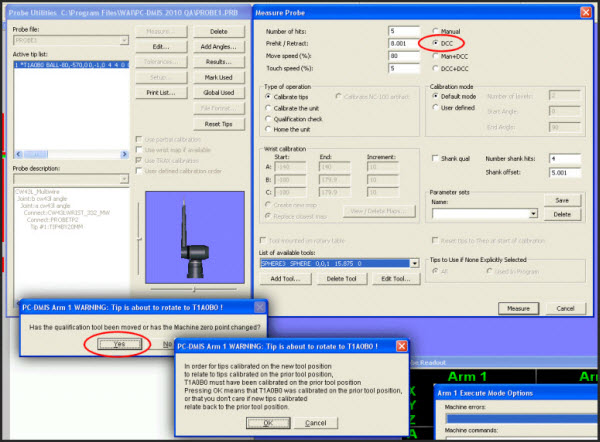
In the Measure Probe dialog box (Insert | Hardware Definition | Probe | Measure button) for the PROBEALL probe, choose DCC.
In the List of available tools, choose SPHERE3.
Click Measure.
When PC-DMIS asks if the qualification tool has moved or the machine zero point has changed, click Yes.
Dialog boxes showing the settings used
DCC Calibration of SPHERE1 Using Arm 1
In the Measure Probe dialog box, in the List of available tools, choose SPHERE1.
Ensure that the IJK orientation of this calibration sphere is correctly set to 0, -1, 0.
Click Measure.
When PC-DMIS asks if the qualification tool has moved or the machine zero point has changed, click Yes.
DCC Calibration of SPHERE2 using Arm 2
Access the Measure Probe dialog box for PROBE2, the probe on Arm 2.
In the Measure Probe dialog box, choose DCC.
In the List of available tools, choose SPHERE2.
Ensure that the IJK orientation of this calibration sphere is correctly set to 0, 1, 0.
Click Measure.
When PC-DMIS asks if the qualification tool has moved or the machine zero point has changed, click Yes.
The next step provides information on mapping the wrists of Arm 1 using SPHERE1.