 and then enter a value.
Once you select the Gage Axis, you can define the Point of Interest (POI).
There are two methods to define the POI.
Method 1:
In the Thickness Gage dialog box, from the CAD View in the Graphic Display window, click the primary feature. The software completes the Gage Distance value based on the mouse-click position on the CAD.
Method 2:
In the Thickness
Gage dialog box, click the Add button
and then enter a value.
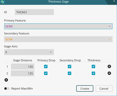
Once you define a POI, PC-DMIS creates these commands:
THCKG1_DP1 (Drop Point Primary) - This is the nominal pierce value and the actual primary curve value at the Gage Distance.
THCKG1_DS1 (Drop Point Secondary) - This is the nominal pierce value and actual secondary curve value at the Gage Distance.
THCKG1_THP1 (Thickness Point of THCKG1_DP1) - This is a duplicate point of THCKG1_DP1.
THCKG1_THS1 (Thickness Point Secondary) - This is the nominal pierce value and actual secondary curve value normal to THCKG1_THP1.
To report the thickness and gage position, the Thickness Gage command uses a Gage Axis method:
If the input features are in the XY plane (Z is constant), the Gage Axis option is XY.
If the input features are in the YZ plane (X is constant), the Gage Axis option is YZ.
If the input features are in the XZ plane (Y is constant), the Gage Axis option is XZ.
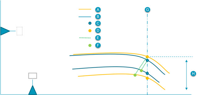
A - Actual
B - Nominal
C - Nominal Drop Point XYZIJK
D - Actual Drop Point XYZIJK
E - Normal to Top Curve
F - Thickness Point XYZIJK
G - Gage Distance
H - Drop
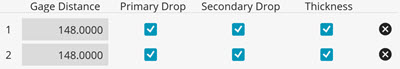
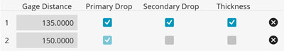
You can determine which dimensions to report with the Primary Drop, Secondary Drop, and Thickness check boxes.
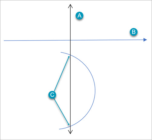
You must use simple curves to create a POI. A simple curve is a curve that has only one intersection along any line normal to the gage axis.
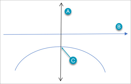
A - Vector normal to the gage axis
B - Gage Axis
C - Single intersection point along the line normal to the gage axis
Example of a simple curve
A - Vector normal to the gage axis
B - Gage Axis
C - Multiple intersection points along the line normal to the gage axis
Example of a non-simple curve
When you manually enter the gage distance value or click the CAD to create a POI, if the primary or secondary curve is not simple, PC-DMIS displays an error message and does not create a POI.
PC-DMIS
The features and gage axis represents an unsupported shape. Features with curves which have multiple intersections along any line normal to the gage axis are not supported.
The primary curve nominal data must also be smooth relative to the thickness. When you enter the Gage Distance value, or click the CAD to create a POI, if the primary curve is not smooth enough, PC-DMIS displays an error message and does not create a POI.
PC-DMIS
The nominals are not smooth enough to calculate thickness curve.
If a Drop Point or Thickness Point cannot be found on the secondary curve, the software disables the relevant options in the Thickness Gage dialog box.
If PC-DMIS cannot detect a POI, it displays this message:
PC-DMIS
No point of interest found at this gage distance.
You can add the maximum and minimum thickness values between the primary and secondary features into your report.
More: