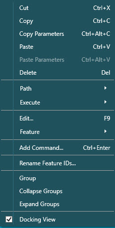
When you select a command item in the Edit window's Summary mode (see "Working in Summary Mode" in the "Using the Edit Window" chapter) and right-click on the command item, the command shortcut menu appears. This menu has the following options:
Summary mode command shortcut menu
The following options are available:
Cut (Shortcut Key stroke: Ctrl + X)
This option cuts the selected command to the Clipboard and removes the command from the measurement routine.
Copy (Shortcut Key stroke: Ctrl + C)
This option copies the selected command to the Clipboard.
Copy Parameters (Shortcut Key stroke: Ctrl + Alt + C)
This option copies the selected parameters to the Clipboard.
Paste (Shortcut Key stroke: Ctrl + V)
This option pastes a command that you previously cut or copied from the Clipboard and places it below the selected command.
Paste Parameters (Shortcut Key stroke: Ctrl + Alt + V)
This option pastes the copied parameters from the Clipboard into the Edit window at the cursor position.
Delete (Shortcut Key stroke: Del)
This option deletes the selected command and any sub-commands out of the measurement routine.
Path | Path Lines
This option shows only the path lines for a range of selected features. See "Showing, Animating, and Moving Path Lines" in the "Editing the CAD Display" chapter.
Path | Collision Detection
This option shows path lines and performs the collision detection for a range of selected features. See "Detecting Collisions" in the "Editing the CAD Display" chapter.
Path | ClearanceCube | Off
Turns the ClearanceCube feature to Off.
Path | ClearanceCube | On
Turns the ClearanceCube feature to On.
Path | ClearanceCube | Starting Face
This option enables you to select the Starting Face to align the ClearanceCube to. The options are -X, +X, -Y, +Y, -Z, +Z, and Off.
Path | ClearanceCube | Ending Face
This option enables you to select the Ending Face to align the ClearanceCube to. The options are -X, +X, -Y, +Y, -Z, +Z, Use Tip Vector, and Off.
Path | Optimize Path
This option only appears if you right-click on a GROUP command. It performs a path optimization on the features inside of the group. For more information, see "Path Optimization for Single Arm with Touch Probe" in the "Using Inspection Plans in PC-DMIS" appendix.
Execute | Execute From Cursor
This option starts the measurement routine at the point of the current cursor location.
Execute | Execute Block
This option executes a designated block of code.
Edit (Shortcut Key stroke: F9)
This option displays the dialog box for the current command object.
Feature | Update Nominals From CAD
This option updates the measurement routine nominals with the imported CAD nominals.
Feature | Override FindNoms
This option overrides the default FindNoms behavior of PC-DMIS during Learn mode and Execute mode. For more information, see "Overriding Found Nominals" in the "Editing a Measurement Routine" chapter.
Feature | Reset Measured Values to Nominal
This option sets all measured values to the measurement routine nominal values.
Feature | Center in CAD
This option pans and rotates the part's CAD model as needed to center the current feature in the Graphic Display window. Once centered, the feature flashes a few times. You cannot undo this pan-and-rotate operation.
Feature | Highlight in CAD (Shortcut Key stroke: Ctrl + Shift + H)
This option highlights the selected feature in the Graphic Display window. It also shows and highlights the feature label if it is hidden. To clear the highlight of the first feature, highlight a second feature.
Feature | UnHighlight in CAD (Shortcut Key stroke: Ctrl + Shift + U)
This option clears the CAD feature that you highlighted through the Highlight in CAD menu item.
Feature | Move Probe to Feature
This option moves the animated probe in the Graphic Display window to the CAD element for the selected feature. It becomes available for selection only in Offline mode and only if you first select a feature command. Other commands are not supported.
Feature | Move To SPH_Tip1
This option only appears when you right-click on an Auto feature. It moves the probe to the center of the selected Auto feature. This action functions the same as the Move To button in the Auto Feature dialog box (Insert | Feature | Auto | <Feature Type>).
WARNING: When you do this, the machine moves. To avoid injury, stay clear of the machine. To avoid hardware damage, run the machine at a slower speed.
Feature | Test SPH_TIP1
This option only appears when you right-click on an Auto feature. It performs a test execution of the selected Auto feature. This action functions the same as the Test button in the Auto Feature dialog box.
WARNING: When you do this, the machine moves. To avoid injury, stay clear of the machine. To avoid hardware damage, run the machine at a slower speed.
Add Command (Shortcut Key stroke: Ctrl + Enter)
This option enables you to add a command to the Edit window from the Add Command dialog box.
STEP 1: Use the search box to type the first few letters of the command. PC-DMIS displays the filtered list.
STEP 2: Select the command from the list.
STEP 3: Press either Ctrl + Enter or Enter to place the new command into the Edit window.
Press Ctrl + Enter to place the command after the command block used to open the shortcut menu.
Press Enter to place the command inside the command block used to open the shortcut menu. The Enter key only functions in this manner if the command you are adding is a type of command that PC-DMIS can insert into another command block. Otherwise, PC-DMIS inserts it after the current command.
Rename Feature IDs
This option enables you to rename multiple feature IDs at the same time.
Group
This option inserts the list of contiguous commands into a user-defined group.
Collapse Groups
This option collapses all expanded user-defined groups. Other expanded items remain expanded.
Expand Groups
This option expands all collapsed user-defined groups. Other collapsed items remain collapsed.
Docking View
This option determines whether or not the Edit window is docked or undocked.
If you deselect this option, the Edit window floats over the Graphic Display window.
If you select this option, you can dock the Edit window to the sides or top or bottom of the Graphic Display window.
For details on how to dock and undock user interface elements, see "Docking and Undocking User Interface Elements".
When you select a command item in the Edit window in Summary mode (see "Working in Summary Mode" in the "Using the Edit Window" chapter) and right-click on the command item, the options on the command shortcut menu change according to the type of command you selected: general, pointcloud, pointcloud cross section operator, or Mesh.
The following shortcut menu appears for pointcloud commands:
_pointcloud.jpg)
Shortcut menu for pointcloud commands
The following options are available:
Show or Hide
This option toggles the labels between shown and hidden. This option is also available for the Mesh commands.
Pointcloud Display
Smooth - This option provides a shaded appearance using the defined COP color.
Flat - This option shows the COP in a non-shaded graphical view. This selection requires the least amount of graphical memory.
Two sided - This option shows a shaded appearance where the scanned side of the part is the defined COP color, and the non-scanned side is a contrasting color.
Mesh display - This option shows the pointcloud as a Mesh display.
The Mesh display option is only available if you have the Mesh license and you scanned the COP using the Mesh display option (Portable only). For details, see "Pointcloud Display Section" in the PC-DMIS Laser documentation.
The Mesh display is a display setting only. The underlying data is a pointcloud.
However, the mesh display is lost, and the display reverts to points if you edit the COP (for example, if you perform any COP operation on the pointcloud).
For more information about the Pointcloud Display options, see "Pointcloud Graphical Representation" in the PC-DMIS Laser documentation.
Pointcloud Cross Section Operator Commands
The following shortcut menu appears for pointcloud cross section operator commands:
_pointcloudop.jpg)
Shortcut menu for Pointcloud Cross Section operator commands
Show Only
This option displays the 2D view of the selected cross section. When you enable the option, PC-DMIS displays a check mark to the left of it. For more information, see "2D View of Cross Sections" in the PC-DMIS Laser documentation.