You can also use BASIC code in the VBS Mini-Editor to dynamically change the value of the gauge at a given time. Suppose you want to create a form that moves the gauge from 0 to 100 percent based on how close a circle's diameter approaches its minimum and maximum allowed tolerances. You can do this by following this procedure:
Step 1 - Create the Form
Create a new form and make sure it's in Edit mode. First, you need to create a variable named MYDIAMETER that takes the diameter value of the circle.
Right-click on the grid and make sure The Frame / The View is selected from the object list on the Properties dialog box.
Expand the Advanced heading in the Properties dialog box. Select the value for the LocalVariables property. The Local Variables dialog box appears.
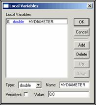
Click the Add button to add a new variable. Select Double from the Type list. In the Name box, type MYDIAMETER. Leave the Value as 0.
Local Variables dialog box showing the MYDIAMETER variable
Click OK to return to the Properties dialog box. The MYDIAMETER variable is now added to the form.
Next, insert a Gauge object into the form.
Select the Gauge object and place and size it as desired. The vertical distance is the total distance the percentile bar can travel.
From the Properties dialog box, ensure that the added Gauge object is selected.
Again, under the Advanced heading on the Properties dialog box, click the MaximumEq property. The VBS Mini-Editor appears; much of it is unavailable for selection.
Select CONST from the list. This value allows you to define the gauge's 100% value.
Type the maximum allowed value for the circle's diameter. This example measures a one inch diameter circle with an allowed tolerance of .010. So, the maximum allowed value would be 1.010.
Click OK to return to the Properties dialog box.
Click on the MinimumEq property. The VBS Mini-Editor re-appears. This value allows you to define the gauge's 0% value.
Select CONST from the list.
Type the minimum allowed value for the circle's diameter. Again, since this example measures a one inch diameter circle with an allowed tolerance of .010, the minimum allowed value would be 0.990.
Click OK to return to the Properties dialog box. Now you need to give the actual value of the gauge the diameter of the circle.
With the gauge object still selected from the Properties dialog box, under the Advanced heading, select the ValueEq property. The VBS Mini-Editor appears; much of it is unavailable for selection.
In the list on the left, select + EQ ($).
In the list on the right, select the <MYDIAMETER>.

Using the VBS Mini-Editor to set the value of the gauge object
Click OK to close the VBS Mini-Editor.
Save the form. This example gives the form the name of gaugetest.form.
Step 2 - Create a Generic Circle Feature
Now, you need to create a generic circle feature inside PC-DMIS. Select PC-DMIS's Edit window and place it in Command mode.
Insert a generic feature by typing GENERIC and then press the Tab key. Initially, a generic point feature appears in the Edit window with the feature's ID selected.
Press F9 to access the dialog box for this generic feature.
In the Feature Type area, select Circle.
In the Data Type area, select Nominal Values.
Type a name for the circle in the Feature Name box. This example uses CIR1 for the feature name.
Type the XYZ and IJK values for CIR1.
Select the Diameter option and give CIR1 a nominal diameter value of 1.
Change any other options as desired and then click OK when finished. The code for the generic circle in your Edit window should look something like this:
CIR1       =GENERIC/CIRCLE,DEPENDENT,RECT,OUT,$
            NOM/XYZ,1,1,0.95,$
            MEAS/XYZ,1,1,1,$
            NOM/IJK,0,0,1,$
            MEAS/IJK,0,0,1,$
            DIAMETER/1,0
Step 3 - Insert an INPUT Comment and Modify Generic Circle
Move your cursor before the CIR1 feature and insert an input comment to take a measured diameter value (since this example is done in Offline mode, the "measured" values are inserted manually). For example:
C1 =COMMENT/INPUT,Please type CIR1's measured diameter:
Now go to the command block for CIR1 and on the last line where it says DIAMETER/1,0 change the second parameter, the measured diameter of 0, to C1.INPUT. This assigns the value from the input comment to CIR1's measured diameter.
DIAMETER/1,C1.INPUT
Now, move the cursor after the CIR1 feature and embed the saved form by selecting the Insert | Report Command | Form menu option.
Step 4 - Insert a FORM/FILENAME Command and Execute
Type FORM and press the Tab key to insert a FORM/FILENAME command block into the Edit window.
Now, in the FORM/FILENAME command where it says PARAM/=, place your cursor immediately before the equals sign and type MYDIAMETER. Then move the cursor immediately after the equals sign and type CIR1.DIAMETER. The code to embed your form should look something like this:
CS1        =FORM/FILENAME=C:\PCDMIS35\GAUGETEST.FORM, AUTOPRINT=NO
            PARAM/MYDIAMETER=CIR1.DIAMETER
            PARAM/=
            ENDFORM/
Mark the newly added commands and then execute the measurement routine. The diameter for CIR1 gets passed as a parameter into the form and the gauge object's percentile dynamically changes depending on the circle's measured diameter.
For example, if the measured diameter for CIR1 was .9987 you would get a form that looks something like this:
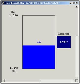
Sample Form Showing the Gauge Object Dynamically Linked to a Feature's Measured Diameter