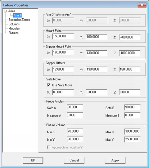
Fixture Properties dialog box - Arm Properties
Set the properties for arms in the Properties dialog box.
Arm Offsets vs Arm1 - This area defines the location of the given arm in relation to the Arm1 coordinates. For example, Arm2 measures the center of a sphere as (X2, Y2, Z2), while Arm1 reads (X1, Y1, Z1). The arm offset is (X2-X1, Y2-Y1 , Z2-Z1). In the case of Arm1, the coordinate values are always (0.0, 0.0, 0.0) since this is the relationship of Arm1 to itself.
Mount Point - This area provides a clearance position where the machine arm can safely be moved to after positioning one or all the columns of a fixture.
Gripper Mount Point - This area defines the location where you can safely remove or attach the locator for manual systems.
Gripper Offsets - This area defines the values of the gripper offsets after calibration. The gripper offset is treated the same as a probe offset. The center of the gripper is linked to the machine.
Safe Move - This area specifies the XYZ location that the machine moves to. If you choose to insert intermediate moves, this helps to eliminate collisions in your fixturing sequence. Select the Use Safe Move check box to enable safe moves.
Probe Angles - Use the Safe A and Safe B boxes to define the clearance position of the wrist when the gripper is enabled. Use the Measure A and Measure B boxes in this area to define the measuring position of the wrist when the gripper is disabled.
Fixture Volume - This area defines the Min and Max values for the fixture volume in terms of XY coordinates. The Approach in negative Y check box is used for the slave arms of a master-slave system. Reversing the direction that the slave machine approaches may be needed to cause the machine to move in the correct direction.
Click Apply to apply the changes that have been made for this arm.
Click OK when you are done changing all fixture properties.