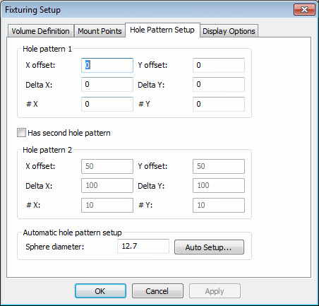
Fixturing Setup dialog box - Hole Pattern Setup tab
Specify properties for the hole pattern for manual (mechanical) systems. The hole pattern refers to the threaded holes on the table to which the column is attached. The column can shift within a defined range on the slide that is attached to the column base. The column clamps to an insert that is screwed into one of the threaded holes in the hole pattern. You can have up to two regular patterns.
To define the hole patterns, follow one of the following methods:
Method 1
Specify the X offset and Y offset values to define the center of the first hole in the pattern. This can be done via calibration/measurement.
Define the Delta X and Delta Y values, which represent the X and Y pitch.
Enter the number of rows in the X direction (#X) and Y direction (#Y).
Click OK or Apply to accept any changes that you made.
Method 2
Specify the Sphere diameter value in the Automatic hole pattern setup area. This provides the diameter of the sphere that your calibrated tip measures as part of the auto setup process. The sphere is attached to the leading hole of the pattern. Measuring the center of the sphere establishes the XY position of the leading hole.
Click the Auto Setup button to access the guided procedure to calibrate one or more hole patterns.
Follow the guided procedure as outlined in the sequence of screen shots (HolepatternSetup1 through HolePatternSetup5).