To calibrate the gripper, open the Calibrate Columns tab in the Fixturing Setup dialog box. For details on how to calibrate fixturing components, see the topic "Calibrating Fixturing Components in PC-DMIS".
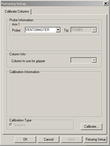
Fixturing Setup dialog box - Calibrate Columns tab
Follow this procedure to calibrate your grippers:
Select the probe file from the Probe list in the Probe Information area.
Select the tip you'll use to measure from the Tip list in the Probe Information area.
If the rack is loaded and you know the column locations, select the column that you want to use from the list in the Column Info area to calibrate the gripper. By default, PC-DMIS selects the Grippers option in the Calibration Type area.
Click the Calibrate button.
The calibration process begins with a prompt for you to load the column onto the gripper. Manually load the column onto the gripper and then click OK to proceed.
The machine moves the column 200 mm from the edge of the fixturing volume in the Y axis and at the X axis where you loaded it.
The machine then moves to the edge of the usable fixture volume and back to its original starting point. This simulates the moves the machine takes when it actually places a fixture, and it improves the gripper calibration.
The machine then unloads the column, and the probe changes to the selected measure tip.
PC-DMIS prompts you to take a single hit on the column sphere.
Take a single hit on the column sphere. PC-DMIS repeats the above step two more times, with the column loaded, moved, unloaded, and measured automatically in DCC mode.
PC-DMIS stores the result, the average of the three movement and measurement iterations, in the Fixturing Server application. This application manages the fixturing data. You can run it on the same computer as PC-DMIS or from a completely different location over a network. The Fixturing Server application differs from the Fixture Server Interface application, which is used to configure your Flexible Fixturing system. See the "Using Fixturing System Setup" topic for more information.