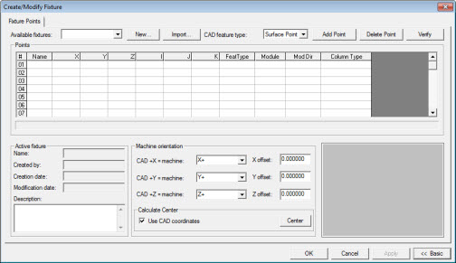
To create a new fixture, select the Insert | Hardware Definition | Fixture menu option to open the Create/Modify Fixture dialog box.
Create/Modify Fixture dialog box
Click New to open the New Fixture dialog box.
Type a name in the Name box for the new fixture.
Type your name or operator number in the Created By box.
Type a Description for the new fixture.
Click OK. PC-DMIS creates your fixture definition and adds it to the Available fixtures list.
To define each fixture point, complete the information in the Points area. For information on how to do this, see "To Specify Fixture Points".
Once you have added all the fixture points, specify the machine's XYZ axes that match the CAD model's XYZ axes. To do this, select the axes from the CAD +X = Machine, CAD +Y = Machine, and CAD +Z = Machine lists in the Machine Orientation area.
For each CAD axis, specify the appropriate offsets in the X Offset, Y Offset, and Z Offset boxes. The offsets are based on the machine's home position.
If you don’t know a specific offset to use, click the Center button to have PC-DMIS calculate the offset for you. These calculated offsets place your part in the center of the machine volume. If a CAD model is loaded in the measurement routine, and you mark the Use CAD coordinates check box, the CAD coordinates are considered when calculating the center. If this check box is cleared, and the CAD is loaded in the measurement routine, the calculation of the center uses only the coordinates of the Fixture Points. The check box is unavailable if the CAD is not loaded in the measurement routine.
Once you have defined all the elements of the fixture, click the Apply button to save your changes. This saves the fixture definition to the server and verifies your fixture to make sure it is legal on your machine.