 button to open the Relative Feature dialog box
to select the feature or features to which the Auto feature is relative.
Multiple features can be defined for each axis (XYZ) relative to your
Auto feature.
button to open the Relative Feature dialog box
to select the feature or features to which the Auto feature is relative.
Multiple features can be defined for each axis (XYZ) relative to your
Auto feature.Best Fit Math Type
A laser Auto feature Circle also allows you to define the Best Fit Math Type. For details, see "Best Fit Type for Circle" in the "Constructing New Features from Existing Features" chapter in the PC-DMIS Core documentation. Valid options for the Perceptron system are Maximum Inscribed, Minimum Circumscribed, and Least Squares.
Starting with PC-DMIS 2019 R2, PC-DMIS no longer supports the Perceptron laser sensor. While you may still be able to install PC-DMIS 2019 R2 and later, PC-DMIS displays an error if you attempt to run measurement routines that use the Perceptron scanner. For additional information, please contact Technical Support.
Relative to
This option allows you to keep the relative position
and orientation between a given feature (or features) and the Auto feature.
Click the
button to open the Relative Feature dialog box
to select the feature or features to which the Auto feature is relative.
Multiple features can be defined for each axis (XYZ) relative to your
Auto feature.
Analysis Area
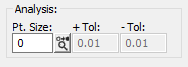
The Analysis area allows you to determine how each measured hit/point is displayed.
Pt. Size - This value determines how big the measured points are drawn in the CAD tab. This value specifies the diameter in the current units (mm or inch).
 Graphic Analysis button - When this button is
switched on, PC-DMIS does a tolerance check on each point (how far from
the calculated actual feature it is) and draws it in the appropriate color
based on the current defined color range for the dimension.
Graphic Analysis button - When this button is
switched on, PC-DMIS does a tolerance check on each point (how far from
the calculated actual feature it is) and draws it in the appropriate color
based on the current defined color range for the dimension.
+ Tol - This option provides the positive tolerance from the nominal. It is specified in the current measurement routine's units. Points that are greater than this value from the nominal are colored based on the standard PC-DMIS positive-tolerance color.
- Tol - This option provides the negative tolerance from the nominal. It is specified in the current measurement routine's units. Points that are less than this value from the nominal are colored based on the standard PC-DMIS negative-tolerance color.
For information on editing dimension colors for the positive and negative tolerances, see the "Editing Dimension Colors" topic in the "Editing the CAD Display" chapter in the PC-DMIS Core documentation.