Cylinder Measurements
Adjust the processing window in the Laser View to include as much of the cylindrical surface as possible. The laser plane must be roughly normal to the cylinder axis ( < 30 degree deviation). Depending on the diameter of the cylinder, PC-DMIS takes one of these paths when performing the measurement:
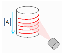
Path 1: Single Scan
Cylinders with a diameter less than the usable portion of the stripe. A is the scan motion.
Path 2: Multiple Scans
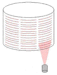
Cylinders with a diameter larger than the usable portion of the stripe
When you perform a laser scan of a feature with a Tesastar wrist, the best scanning direction may be along the feature’s vector or normal to it. This however depends on the ability of the head to rotate to an angle that allows you to scan in a direction normal to the stripe’s orientation.
 Example
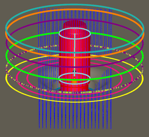
path creation for directly measured Cylinder laser feature when using
an Auto Wrist:
Example
path creation for directly measured Cylinder laser feature when using
an Auto Wrist:
Stud Measurements
Single Scan
Adjust the processing window in the Laser View to include as much of the cylindrical surface as possible. The laser plane must be roughly 30-60 degrees to the cylinder's axis. The scan must capture the region on the base plane of the stud where the cylinder is mounted.
Single pass laser scan on stud cylinder