You can also access the Gage dialog box in these ways:
Click the Caliper button (
 )
from the QuickCloud toolbar.
)
from the QuickCloud toolbar.From the QuickMeasure toolbar, click the Gage drop-down arrow, and then click the Caliper button.
Before you create a Caliper, you must have either a COP, Mesh, or a COPOPER (such as the COPSELECT, COPCLEAN, or COPFILTER) object already defined in your measurement routine. A CAD model is not required.
To create a Caliper feature:
Select the Caliper option from the Insert | Gage menu. The Gage dialog box opens.
You can also access the Gage dialog box in these ways:
Click the Caliper
button ()
from the QuickCloud toolbar.
From the QuickMeasure toolbar, click the Gage drop-down arrow, and then click the Caliper button.
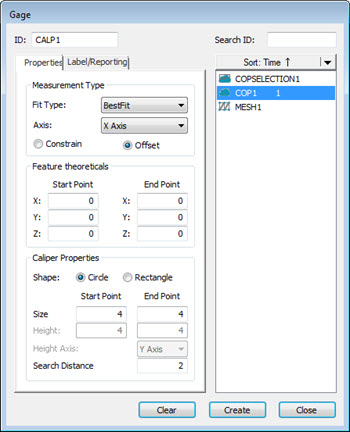
Gage dialog box
Select the COP, COPOPER, or Mesh data object to use.
In the Measurement Type area, from the Fit Type list, select a type.
Select an axis in the Axis list, and then select the Constrain or Offset option:
Select the Constrain option to make the two end points exactly opposite one another along the selected axis.
Select the Offset option to allow the two end points to be offset from each other in position. The measured length remains along the selected axis.
In the Caliper Properties area, select the Circle or Rectangle shape option.
Edit the current value, or select the appropriate values for the following options:
Circle-shaped caliper tip options
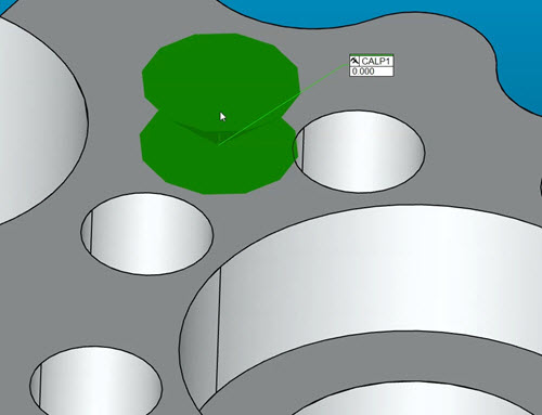
Size: The default value is 4 mm for the Start Point and End Point options. You can set the start and end points of the caliper to different sizes depending on the CAD surfaces.
Example of a caliper created with different start and end point sizes
For non-planar surfaces, you should set the size to a larger value, such as 8-10 mm, to capture the high point. For planar surfaces, you can set it to a smaller value, such as 2 mm.
Search Distance: The default value is 2 mm. This value defines the length, from nominal, on either side of the picked point. The search distance along with the caliper tip shape creates a cylindrical zone. All data within this zone is evaluated to determine the caliper high point.
Rectangle shaped caliper tip options
Width: The default value is 4 mm for the Start Point and End Point options. The value sets the width of the caliper tip's start and end points.
Height: The default value is 4 mm for both the Start Point and End Point. The value sets the height of the caliper tip's start and end points.
For non-planar surfaces, you should set the width and height to a larger value, such as 8-10 mm, to capture the high point. For planar surfaces, you can set the width and height to a smaller value, such as 2 mm.
Height Axis: The default value depends on the Axis option you select in the Measurement Type area. From the list, select the option to define the axis that controls the rotation of the rectangle.
Search Distance: See the description in the Circle-shaped caliper tip options section.
Changes to any of the Gage dialog box properties become the default values the next time the dialog box opens.
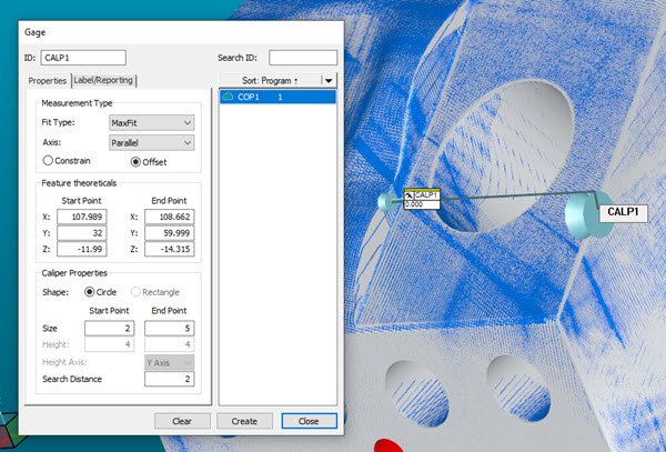
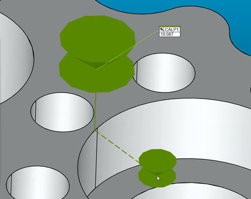
From the Graphic Display window, click to define the start point. To remove the first selected point, press the Delete key.
Move your cursor to the second location, and then click to define the end point. As you move the cursor, the length value updates in the Graphic Display window. If the selected object (COP or Mesh) contains data, the length that is shown is the measured value. If the selected object is empty, and a CAD model is used, the length value that is shown is the nominal value.
You can also enter the XYZ values for each in the Start Point and End Point XYZ boxes.
Caliper line thickness
You can set the thickness of the Caliper line through the OpenGL tab of the CAD and Graphic Setup dialog box (Edit | Graphic Display Window | OpenGL). For details, see the topic "Changing OpenGL Options" in the "Setting Your Preferences" chapter of the PC-DMIS Core documentation.
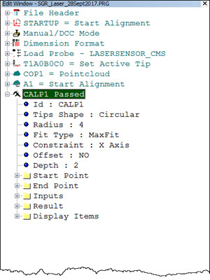
Click Create to define the caliper and add it to the commands in the Edit window.