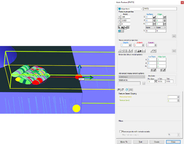
Depth: This defines the depth to use when calculating the edge point. This corresponds to the blue graphical visualization in the Graphic Display window. A depth of 0 will cause this feature to be calculated at the surface plane height, using data found at the lowest possible depth from the surface plane. A depth of any other value will cause it to be calculated at that depth.
Spacer: This controls the size of the area PC-DMIS uses to calculate the feature normal. This corresponds to the purple graphical visualization in the Graphic Display window.
Indent: This lets you define the location of the area PC-DMIS uses to calculate the feature normal. This corresponds to the red graphical visualization in the Graphic Display window.
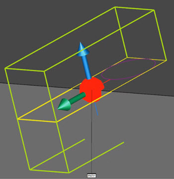
Sample edge point with Depth, Spacer, and Indent graphical visualizations used in the Graphic Display window
Notes on Graphical Analysis and Feature Extraction of Edge Points
If you don't see some graphical analysis points computed to the edge plane, consider the following:
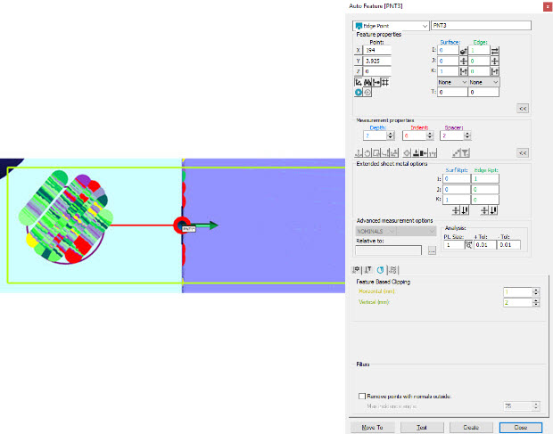
Edge Line Points - All the edge line points on the reference plane returned by the feature extractor are displayed. For analysis, PC-DMIS computes the edge line points using the distance (Indent value) from the reference plane center (center of the circular surface area defined by the Spacer value) to the edge line.
Reference Plane Points - If the Spacer value is 0.0 then the reference plane points are not displayed. If the Space value is not 0.0 then PC-DMIS extracts the reference plane points from the pointcloud, applying the following rules and using the plane statistical data returned by the feature extractor:
Rule 1: PC-DMIS discards all points that are
outside of an  imaginary
cylinder.
imaginary
cylinder.
Rule 2: PC-DMIS discards all points with a
distance from an imaginary
plane greater than the maximum plane error value.
Rule 3: PC-DMIS uniformly reduces any remaining points that are higher than the allowed number (19900) to the allowed value.
For analysis, PC-DMIS computes each reference plane point using the distance from the reference plane and the measured surface plane.
The following two images show the Edge Point laser graphical analysis: