 ) on the Laser Scan Properties
tab.
) on the Laser Scan Properties
tab.You can extract a laser Auto Surface Point from a mesh data object with the Laser Auto Surface Point dialog box.
When you extract the laser Auto Surface Point from
a Mesh data object, PC-DMIS first considers all the triangle vertices
inside the extraction zone, defined by the horizontal and vertical clipping.
To view the points that fall within the extraction zone, click the Show/Hide segregated points button () on the Laser Scan Properties
tab.
To get a more accurate result on a curved surface when you extract an Auto Surface Point from a Mesh, use a smaller horizontal clipping zone to limit the points (vertices) that PC-DMIS uses to calculate the measured value.
For example, when you use a small clipping zone, PC-DMIS uses points close to the nominal location to calculate the deviation. This results in a more accurate measurement on a curved surface:
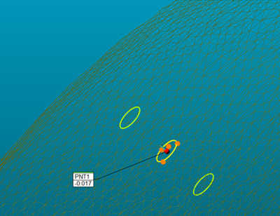
Surface point with small (0.25mm) horizontal clipping
However, if you use a larger horizontal clipping zone, PC-DMIS uses more points to calculate the deviation. Avoid this when you measure points on a curved surface.
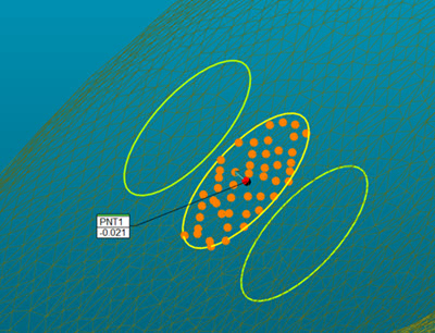
Surface point with larger (1.0mm) horizontal clipping zone
To extract a Surface Point from an existing Mesh:
Click the Surface menu option (Insert | Feature | Auto | Point) to open the Auto Feature dialog box. If you don't see the advanced options in the dialog box, click the Show advanced measurement options button.

Auto Feature dialog box for Surface Point with the advanced measurement options
Select the Mesh reference for the surface point from the Reference list.
From the Graphic Display window, click the CAD to select the point nominal location and vector.
Click the Show/Hide segregated points button to view the points which fall within the extraction zone.
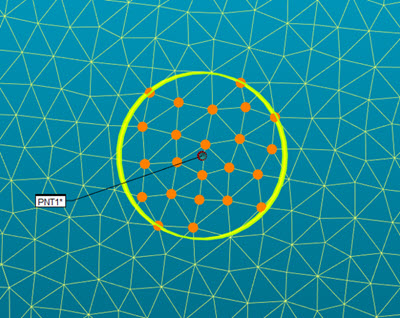
Example of the extracted points that fall within the extraction zone
If the number of vertices within the zone is less than three, then the clipping zone will intersect the Mesh and use the intersection points for the Auto Surface Point feature measurement.
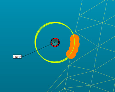
Example of the extracted points that fall within the extraction zone with less than three vertices
Enter the necessary information in the Probe Toolbox tabs. Cycle through the Laser Scan Properties, Laser Filtering Properties, and Laser Clipping Region Properties tabs to enter the information.
If desired, click the Test button to test the feature.
WARNING: When you do this, the machine moves. To avoid injury, stay clear of the machine. To avoid hardware damage, run the machine at a slower speed.
Click Create and then Close.