
Feature Based Clipping area for non-plane Auto features
PC-DMIS can clip laser data in both the horizontal and vertical directions when you type a distance in the Horizontal box and, when available, the Vertical box. This distance clips all of the laser data outside of the defined distance and excludes that data when it extracts the feature.
Alternatively, for 3D features, you can clip data within an offset boundary around all of the CAD elements on a surface. This is also termed CAD segregation. For information on this offset boundary, see "CAD Offset" below.
For the Cone Auto feature:
The value for the Horizontal option defines how much larger the circular boundary (within which the feature points lie) is than the theoretical diameter.
The value for the Vertical option defines how much longer the cylindrical boundary (within which the feature points lie) is than the theoretical length.
Horizontal and Vertical Clipping
All of the Auto features support horizontal clipping. These features support vertical clipping:
Circle
Cone
Cylinder
Polygon
Edge Point
Round Slot
Square Slot
Surface Point
Plane
PC-DMIS shows the clipping distances defined in the feature based clipping rings as colored rings. The horizontal clipping appears as a yellow ring, and the vertical clipping appears as a light-green ring.
Horizontal Inner Clipping
For inner features only, you can apply the horizontal inner clipping which appears as an innermost yellow ring.
These features support horizontal inner clipping:
Circle
Polygon
Round Slot
Square Slot
You can assign the size of the horizontal inner clipping between zero and half of the nominal size of the feature. The nominal size of each feature is defined as:
Diameter for Circles
Inner Diameter for Polygons
The shortest value between the Width and Length for Round Slots or Square Slots
The Horizontal Inner Clipping parameter is available in the Feature Based Clipping area of the Feature Extraction tab. You can also use the Inner_Horizontal_Clipping entry in the Settings Editor to set this value. For details, see the "Inner_Horizontal_Clipping" topic in the PC-DMIS Settings Editor documentation.
Clipping Examples
 and vertical clipping ring")
Sample Circle Auto feature with:
A - Horizontal Outer Clipping Ring
B - Vertical Clipping Ring
C - Horizontal Inner Clipping Ring

Sample Plane Auto feature with horizontal and vertical clipping enabled
Typical Edit window command for a Circle Auto feature:
CIR1 =FEAT/LASER/CIRCLE/DEFAULT,CARTESIAN,IN,LEAST_SQR
THEO/<65,0,-25>,<0,-1,0>,38
ACTL/<64.929,0.049,-24.725>,<0.000189,-0.9999997,0.000754>,38.374
TARG/<65,0,-25>,<0,-1,0>
DEPTH=0,START ANG=0,END ANG=360
ANGLE VEC=<1,0,0>
DIRECTION=CCW
SHOW FEATURE PARAMETERS=YES
SURFACE=THICKNESS_NONE,0
RMEAS=NONE,NONE,NONE
GRAPHICAL ANALYSIS=YES,1,0.01,0.01
SHOW_LASER_PARAMETERS=YES
REFERENCE ID=COP1
SOUND=OFF
HORIZONTAL CLIPPING=2.5,VERTICAL CLIPPING=1,INNER HORIZONTAL CLIPPING=1
RINGBAND=ON,INNER OFFSET=1,OUTER OFFSET=2
OUTLIER_REMOVAL=OFF
REMOVE POINTS WITH NORMALS OUTSIDE=OFF

Feature Based Clipping area for Plane Auto feature
You can enable the CAD offset option for all 3D Auto features and all 3D Constructed Extracted features (Plane, Cone, Cylinder, and Sphere). The CAD offset option provides a way for PC-DMIS to "shrink away" from the selected CAD face boundaries and eliminate points which are within the offset distance to the edges of the feature.
When you select this check box, PC-DMIS creates a yellow offset boundary around each feature in the CAD model on the surface.

Example of a Plane Auto feature with CAD-based clipping enabled
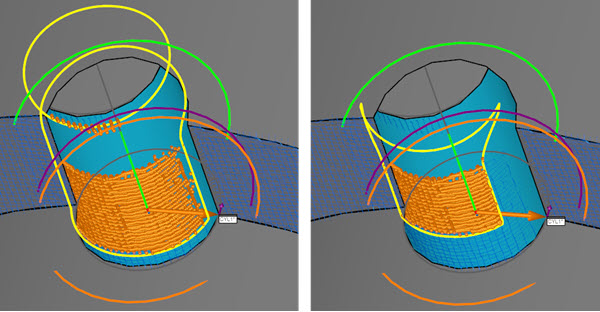
Example of a Cylinder Auto feature with CAD offset of 1 (left) and CAD offset 3 (right)
PC-DMIS draws the boundary around the selected surface to show the area of the considered points. You must select a CAD face when you use the CAD offset option.
PC-DMIS clips the laser data that falls inside of an offset boundary for all of the features in the CAD model on a surface. PC-DMIS uses the data outside of the offset boundary to solve the plane.
For example, consider the image below. The image shows a section of a sample part. The section indicates the data that PC-DMIS would use to create the Plane Auto feature:
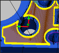
Note that the translucent orange overlay on the image is for clarification only; it is not visible in PC-DMIS.