If you don't have a defined laser sensor, use the Probe Utilities dialog box to define it. This process creates a probe file.
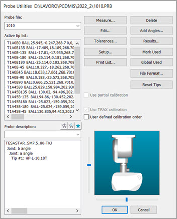
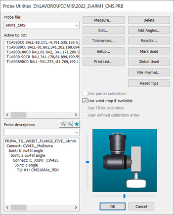
Select the Insert | Hardware Definition | Probe menu option to open the Probe Utilities dialog box. (This dialog box automatically opens whenever you create a new measurement routine.)

Probe Utilities dialog box for an indexable head

Probe Utilities dialog box for the CW43L
In the Probe file box, type a name that best describes your laser sensor.
From the list of components at the bottom, select the No probe defined text to highlight it.
From the Probe Description list, select the appropriate probe. You can mount the CWS or WLS sensor on a wrist with a TKJ connector, or on OPTIV_FIXED on multi-sensor machines.
As needed, select additional components in the same manner for "empty connections" until you finish defining the probe. A defined probe shows a tip in the Active Tip List.
Once you define the tip, the software no longer shows the probe image. This makes it so that the graphical image of the probe does not obstruct the view of the part during measurement. However, if you want to enable the display of probe components, double-click on the probe component to open the Edit Probe Component dialog box. Mark the Draw this component check box.
If you use a PH10, Tesa, or continuous-type wrists with a C joint, you need to verify that the joint angles are properly adjusted for visual purposes. Otherwise, PC-DMIS can't properly correlate the sensor’s data to the machine position. If your probe is not rotated correctly about the joint, you can manually provide the extra rotation. To do this, right-click on the component and change the Default rotation angle about connection value to reflect the needed rotation.
The probe file does not define the orientation of the sensor about the joint; it only defines the probe vector.
For additional information on how to define probes, see the "Defining Hardware" section in the PC-DMIS Core documentation.